

 English
 français
 Deutsch
 español
 العربية
 中文
中文
If you are in the power industry, you must have heard of reactive power compensation. But you may not know much about it.
What is reactive power compensation?
Electricity from the power grid comes in two types: First, there's active power. This is the electricity that does the direct work, turning into motion, heat, chemicals, or sound to power machines and appliances. We call this "active" because it actively does stuff.
Then there's reactive power. This is a bit trickier—it uses electricity too, but mainly to change its form. Although it doesn't directly power anything, reactive power is vital for many electrical devices to function properly. It's constantly swapping back and forth between different energy forms within the grid. A good way to think about reactive power is how it's used to create magnetic fields around transformers and electric fields in capacitors.
Reactive power isn't as straightforward to measure as active power, but it plays a crucial supporting role in keeping our electrical systems running smoothly.
Reactive power can be expressed as
Q = S sin ϕ Q = VI sin ϕ Q = P tan ϕ Where S = apparent power and P = active power.

The History

Observing the diagram that illustrates the various approaches to addressing reactive power compensation, a significant transformation emerged in the 1970s. Economic considerations, specifically high costs related to the production and operation of traditional rotating machinery, actively drove the transition. Consequently, static compensation techniques, characterized by their lack of moving components and hence greater efficiency, started gaining prominence. In the subsequent years, this sphere has witnessed three pivotal advancements, marking substantial progress in enhancing and refining this technology.
The first generation
Mechanical switching-based passive compensation devices, being slow in reactive power compensation, have largely been phased out in current times.
The second generation
The Static var compensator , or SVC, is a device that helps control electricity flow quickly. It uses special parts called thyristors. Right now, most places use two main parts: TCRs and TSCs. But these have some problems – they don't always add just the right amount of power, it's hard to make them bigger when needed, and they can get very hot.
Let's break down how TCRs work:
TCRs are pretty smart gadgets. They control something called "turn-on time" for tiny parts called thyristors. This timing tweak affects how much 'reactive power' the TCR deals with. Now, think of reactive power as a helper energy—it doesn’t do the heavy lifting like making motors spin, but it's essential for keeping the electricity grid stable and running smoothly.
Here's the clever bit: TCRs have a nifty way of managing any extra energy floating around. They make sure there's not too much or too little, keeping everything nicely balanced. It's like having a friend who makes sure your party always has just enough food and drinks—never too much waste or not enough fun.
If you want a peek behind the scenes, there's even a picture that shows what the insides of a TCR look like. It might seem complex, but remember, it's all about keeping that electric flow smooth and steady!
We need to find better ways to solve these problems in the future. That means making devices that add just the right amount of power, are easy to make bigger, and don't waste energy by getting too hot.

TSC: generally, the filter of multiple branches is designed according to a certain proportion, which is capacitive at the fundamental frequency, and the reactive power output of the compensation device changes in stages. The filter branch offsets and tunes under certain harmonics, and filters the harmonics at the same time. TSC can only be switched in groups and must be coordinated with TCR for continuous adjustment. TSC has three basic circuits, as shown in figure. Figure left shows the star with neutral connection, figure mid shows the external connection of triangle, which is called angular external connection, and figure right shows the internal connection of triangle, which is called angular internal connection. On the basis of these three circuits, many other topologies are derived, such as replacing the thyristor in each phase with a diode, or removing the thyristor switch of a phase to save cost. The selection of topology should be comprehensively considered in combination with the actual situation of on-site load and technical and economic factors.

The third generation
Static Var Generator(SVG, etc.) of self reversing converter is the best var compensation device at present. This kind of device usually works by connecting the self commutating bridge circuit in parallel with the power grid. By adjusting the phase and amplitude of the output voltage on the AC side of the bridge circuit, or directly controlling its AC side current, the circuit can absorb or send out reactive current that meets the requirements, so as to realize the purpose of dynamic reactive power compensation.
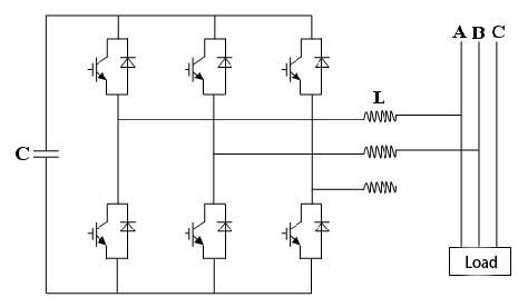
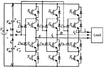
Two level basic circuit diagram Three level basic circuit diagram
YT Power Quality Solutions
Based on the principle of voltage source inverter, YTPQC-SVG static var generator adopts insulated gate bipolar transistor (IGBT) to control the amplitude and phase of AC voltage of the inverter, so as to realize reactive power compensation and three-phase load balance. Because the switching frequency of IGBT is very high (up to 25.6khz), SVG can compensate fast reactive load and realize high-precision compensation. SVG is the best product in the field of reactive power control.


 IPv6 network supported