

 English
 français
 Deutsch
 español
 العربية
 中文
中文
Power Quality Survey: A Comprehensive Practical Guide from
Planning to Implementation
The stable operation of power systems is the core guarantee for industrial production, commercial operations, and even daily life. However, power quality issues such as voltage sags, harmonic pollution, and grounding abnormalities often lead to equipment failures, reduced production efficiency, and even safety hazards. As a key means to identify and solve such problems, power quality surveys directly determine the efficiency and effectiveness of problem-solving through their systematicness and professionalism. Combining industry standards and practical experience, this article details the complete process, core tools, and key points of power quality surveys, providing actionable guidelines for engineering and technical personnel.
I. Core Value and Basic Framework of Power Quality Surveys
The hazards of power quality problems are concealed and conductive: harmonic interference from one piece of equipment may spread to the entire power distribution system, and loose terminal blocks may cause voltage fluctuations, leading to cascading equipment failures. Through scientific process design, power quality surveys can accurately locate the root causes of problems and avoid resource waste caused by blind rectification. A complete power quality survey follows the principle of "closed-loop management" and consists of six core steps:
1. Survey planning and preparation: Clarify objectives and sort out background information to lay the foundation for the survey;
2. On-site inspection: Intuitively identify potential hazards and optimize monitoring plans;
3. Power monitoring: Collect key data such as voltage and current through professional equipment;
4. Data and inspection analysis: Systematically interpret data and correlate on-site issues;
5. Implement corrective solutions: Adopt targeted technical measures;
6. Verify corrective effects: Confirm problem resolution and form a closed loop.
This process is applicable to both local problem troubleshooting of individual equipment and systematic power quality assessment of the entire plant, serving as a core technical means to ensure the reliability of power systems. II. Core Tools: Professional Equipment is the Premise of Survey Accuracy
The accuracy of power quality surveys relies on professional tools, with different tools undertaking functions such as data collection and hazard detection. Among them, power quality monitors are the core equipment. (I) Basic Tool List
|
Tool Type |
Core Function |
Application Scenario |
|
Power Quality Monitor |
Collect voltage/current data, record events such as sags/swells and harmonics |
Full-process core data collection |
|
Multimeter |
Measure basic parameters such as voltage, resistance, and current |
Rapid troubleshooting of wiring abnormalities |
|
Infrared Scanner |
Detect hidden dangers such as equipment hotspots and insulation aging |
On-site inspection phase |
|
Ground Resistance Tester |
Evaluate the reliability of the grounding system |
Grounding abnormality investigation |
|
Clamp-on Current Probe |
Non-contact current measurement without power outage |
Load current detection |
|
Insulation Tester |
Test the insulation performance of lines |
Hidden danger investigation of wiring systems |
(II) Selection and Application of Monitors
Power quality monitors are divided into portable and fixed types, which should be flexibly selected according to survey scenarios:
- Portable monitors (e.g., Dranetz HDPQ series): Suitable for temporary survey scenarios, featuring flexible installation and supporting remote communication functions such as Wi-Fi and Bluetooth. Operators can remotely set parameters and download data via tablets or mobile phones, reducing exposure time in hazardous environments. Equipped with banana plug voltage interfaces and Rogowski coil current sensors, they can adapt to different wiring scenarios and meet short-term monitoring needs.
- Fixed monitors: Used for long-term continuous monitoring, usually installed at core locations such as the Point of Common Coupling (PCC), UPS rooms, and critical loads. They connect to servers via Ethernet or fiber optic networks to upload data in real time. Multiple fixed monitors can form a distributed monitoring system to achieve real-time monitoring of power quality across the entire plant, facilitating early warning of potential issues. Regardless of the type selected, monitors must comply with the IEC 61000-4-30 Class A standard—an international standard that regulates technical requirements for power quality measurement, ensuring data accuracy and repeatability. Currently, IEEE standards in the United States are gradually aligning with the IEC 61000 series; for example, IEEE 519:2014 has adopted the harmonic measurement methods of IEC 61000-4-7. Therefore, priority should be given to equipment meeting this standard during selection.
III. Detailed Key Processes: Practical Points from Planning to Verification
(I) Planning and Preparation: Clarify Objectives and Understand the Baseline
The core of the planning phase is to "define direction" and avoid blind surveys. First, clarify survey objectives: Is it to solve faults of specific equipment or conduct a baseline assessment of power quality across the plant? Different objectives determine monitoring point selection and monitoring duration. Second, comprehensively collect on-site information:
- Consult equipment operators to understand the time pattern of problems (e.g., whether concentrated at a specific time period or related to the startup of specific equipment) and fault symptoms (e.g., equipment restarts, alarm codes);
- Sort out recent equipment change records, including new loads and line modifications, which may be incentives for power quality issues;
- Confirm the power system topology, identifying the location of the PCC, key feeders, and critical loads to provide a basis for monitoring point layout. The monitoring duration should cover the "business cycle": If the production process operates continuously in three shifts, the monitoring duration should be at least 24 hours; if working conditions change weekly, the monitoring duration should be extended to one week to ensure all potential problem scenarios are captured. (II) On-site Inspection: Discover Dominant Hazards with Vision and Tools
On-site inspection is a key link connecting planning and monitoring. Through visual inspection and tool detection, some dominant problems can be identified in advance, and monitoring plans can be optimized. External inspection should focus on:
- Power access method (e.g., overhead lines, underground cables), location of nearby substations, and whether neighboring factories have equipment that may generate interference;
- Power factor correction capacitors installed by the power company, whose switching behavior may cause voltage fluctuations.
Internal inspection focuses on:
- Power distribution system: Whether terminal blocks are loose, wires are aging, and distribution box covers are properly sealed;
- Key equipment: Whether transformers have abnormal noise or overheating, the operating status of UPS systems, and the installation location of large loads (e.g., air compressors, copiers);
- Wiring conditions: Whether cables are crushed, damp, or have damaged insulation, and whether underfloor or under-carpet wiring is standardized. During inspection, infrared scanners can quickly locate hotspots, and ground resistance testers can check if the grounding system meets standards. Dominant problems identified (e.g., loose wiring) should be rectified in a timely manner before monitoring to avoid affecting the accuracy of monitoring data.
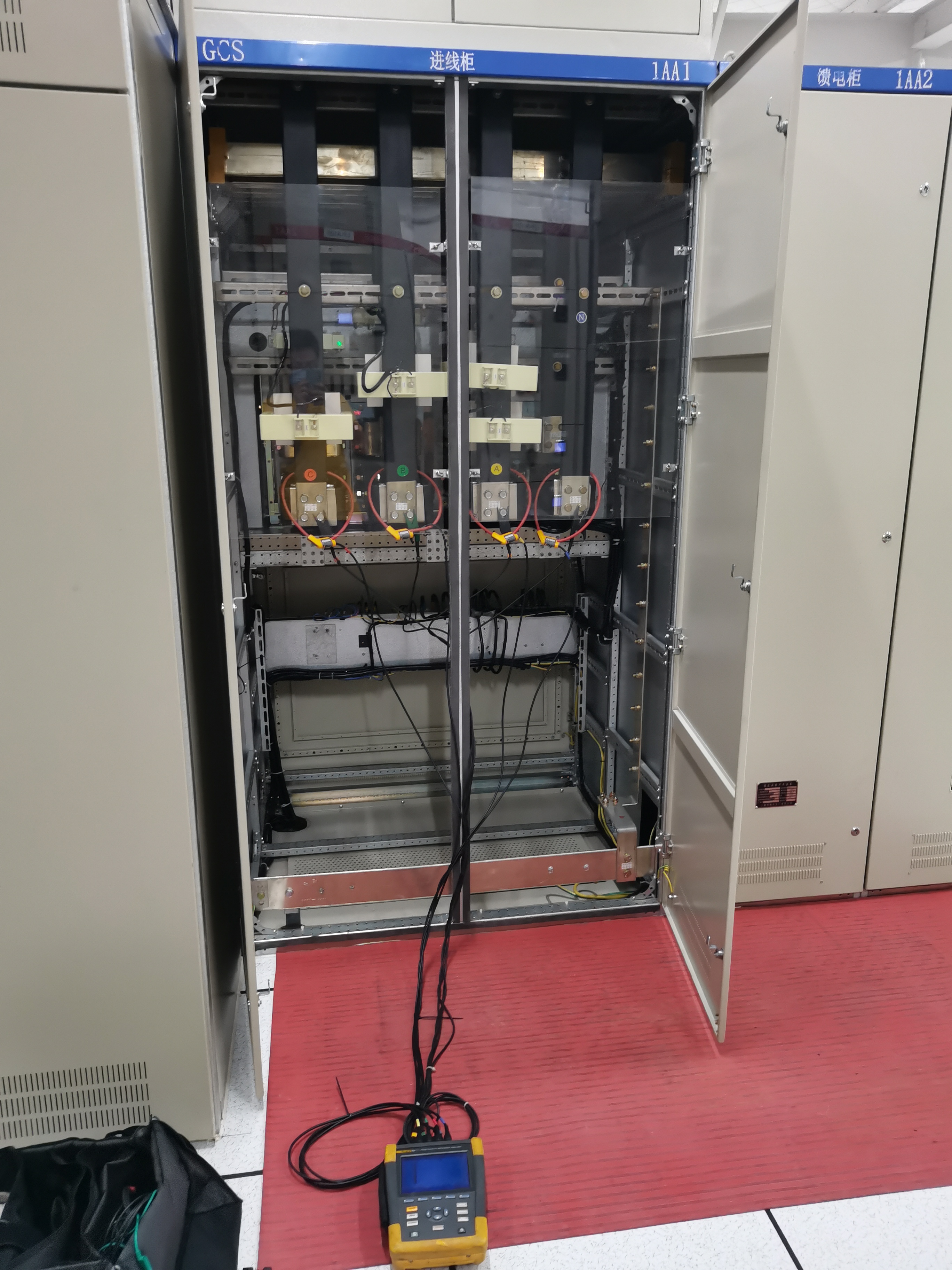
(III) Power Monitoring: Accurately Collect Key Data
The selection of monitoring points directly determines data effectiveness:
- If the problem is limited to a single piece of equipment, the monitoring point should be close to the equipment's power access terminal;
- If the entire plant system is involved, multi-dimensional monitoring points should be arranged at the PCC, each feeder outlet, and critical load terminals;
- Monitor both voltage and current: Voltage data can identify issues such as sags, swells, and harmonics, while current data can determine whether the problem originates from the upstream power grid or downstream loads.
Monitoring should follow a "three-stage" operation:
1. Scope mode observation: Use the monitor's oscilloscope function to intuitively check for voltage and current waveform distortion;
2. Time interval recording: Set a reasonable sampling interval to capture slowly changing parameters (e.g., voltage drift);
3. Threshold-triggered recording: Set thresholds according to equipment tolerance standards to record only key events affecting
equipment operation, avoiding redundant invalid data. During monitoring, regularly check the data collection status and adjust threshold
parameters based on preliminary data to ensure accurate capture of target events.
(IV) Data Analysis: Find the Root Cause from Data
The core of data analysis is "correlation"—combining monitoring data with on-site inspection results and equipment fault symptoms to accurately locate the root cause of problems. The analysis process should follow:
1. Screen key events: Extract power data corresponding to equipment fault periods, focusing on events such as voltage sags, harmonic exceedances, and abnormal grounding currents;
2. Benchmark against equipment standards: Compare monitoring data with the power quality tolerance parameters of equipment to determine which events are direct causes of failures;
3. Classify and organize events: Categorize problems into voltage-related (sags, swells, flicker), current-related (harmonics, three-phase imbalance), and grounding-related (excessive ground resistance, abnormal neutral current) to simplify analysis logic;
4. Integrate inspection results: If monitoring shows voltage fluctuations and aging power factor correction capacitors are found during inspection, it can be initially judged that the problem is caused by poor capacitor switching.
Correspondence between common problems and data characteristics:
- Loose wiring: Random voltage drops and pulse signals in data;
- Excessive harmonics: Distorted current waveforms with Total Harmonic Distortion (THD) exceeding IEC standard limits;
- Neutral line abnormalities: Excessively large neutral line current, causing voltage fluctuations between the neutral line and ground.
(V) Rectification and Verification: Solve Problems in a Closed Loop
Rectification plans should be designed targetedly, with common measures including:
- Hardware modification: Replace aging wires, tighten terminal blocks, upgrade grounding systems, and install harmonic filters;
- Equipment adjustment: Transfer interference source loads to independent circuits and optimize the switching strategy of power factor correction capacitors;
- System optimization: Install UPS or voltage regulators to improve the voltage stability of critical equipment. After rectification, repeat
the power monitoring process to verify effectiveness: If monitoring data shows the disappearance of problem events and the restoration of normal equipment operation, the rectification is effective; if abnormalities persist, re-analyze the data and adjust the rectification plan. For critical facilities in long-term operation, it is recommended to adopt a fixed monitoring system for regular monitoring. Real-time data can warn of deteriorating power quality trends, realizing a shift from "passive rectification" to "proactive prevention."
IV. Core Practical Principles: Avoid Common Pitfalls
Power quality surveys should follow five principles to avoid detours:
1. Reasonableness test: All data interpretation must comply with physical laws; do not distort data to cater to preset conclusions;
2. Tool adaptability: Clarify the range, accuracy, and safety limits of monitoring equipment; avoid over-range use;
3. From easy to difficult: Prioritize investigating simple problems such as loose wiring and terminal overheating before delving into complex issues like harmonics or grounding;
4. Focus on key points: Set reasonable thresholds, prioritize solving key events affecting equipment operation, and avoid "analysis paralysis";
5. Safety first: All operations must comply with safety standards such as NFPA 70E and be performed only by qualified technical personnel to avoid electric shock or equipment damage risks.
Power quality surveys are a systematic project whose success depends not only on professional tools and technology but also on rigorous process management and logical thinking. From clarifying objectives in the planning phase, identifying hidden dangers in the inspection phase, to the full-process closed loop of monitoring, analysis, rectification, and verification, every link is indispensable. With the increasing complexity of power systems and the widespread application of sensitive electronic equipment, the impact of power quality issues has become more prominent. By conducting standardized power quality surveys, enterprises can not only quickly solve existing problems but also establish health records of power systems, providing data support for subsequent operation and maintenance management and upgrading. Ultimately, this achieves the safe, stable, and efficient operation of power systems—both a necessary measure to reduce production risks and an important guarantee to improve operational efficiency for enterprises.


 IPv6 network supported