

 English
 français
 Deutsch
 español
 العربية
 中文
中文
The growing integration of photovoltaic (PV) systems into the grid has created challenges for utility providers. One of the primary concerns is that many power electronics used in these systems consume reactive power, leading to a low power factor and system instability. As a result, power factor correction methods have gained renewed attention. This article outlines the two most commonly used methods for reactive power compensation.
Power factor (PF) is an essential measure of the efficiency of a power system. It represents the ratio of true power, expressed in watts (P), to apparent power, expressed in volt-amperes (S). Apparent power is a combination of true power and reactive power, which is measured in volt-ampere reactive (VAR or Q).
Power factor affects the system's overall efficiency, with lower power factors indicating less efficient energy usage. A power factor of one (unity) represents the most efficient operation, while inductive loads cause a lagging power factor, and capacitive loads create a leading power factor. Resistive loads typically maintain a unity power factor.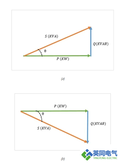
Figure 1. (a)leading power factor. (b)-lagging power factor
Power factor correction (PFC) aims to bring the power factor as close to unity as possible. Poor power factor can lead to higher energy costs, reduced equipment lifespan, and the need for oversized electrical infrastructure like cables and transformers. For instance, industrial equipment such as induction motors, arc lamps, and machinery operating at low loads often suffer from a low, lagging power factor. To account for this, utilities typically impose higher charges on consumers with poor power factor, using a maximum demand or KVA tariff.
Equipment running at a low power factor is prone to overheating, leading to reduced operational life. Both utilities and consumers therefore strive to improve power factor and achieve greater system stability and cost savings.
The underlying principle of all PFC methods is simple: for every inductive load that causes a lagging power factor, a capacitive load with a leading power factor must be connected in parallel to bring the power factor closer to unity.
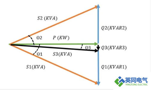
Figure 2. S1 represents the power of a load, Q1 is the lagging reactive power, and cosθ1 indicates the power factor. By adding a leading load with reactive power Q2, the system forms S3, which represents the total power. This reduces the overall lagging reactive power to Q3, improving the system's power factor to cosθ3, bringing it closer to unity at P after the correction.
There are several methods to improve power factor, but the two most common are capacitor banks and synchronous condensers.
Capacitor banks consist of multiple capacitors that store energy and provide reactive power to the system. They can be connected in either a delta or star (wye) configuration. Power capacitors are rated in KVAR, representing the amount of reactive power they generate.
A formula is used to calculate the reactive power (KVAR) a capacitor provides based on its capacitance (C), the system voltage (V), and the frequency (f):
KVAR=C×2π×f×V2×10−9\text{KVAR} = C \times 2\pi \times f \times V^2 \times 10^{-9}10−9
Capacitor banks are usually designed to operate in stages, with each stage delivering a different level of reactive power. This staged approach helps accommodate varying power needs within a system. Capacitor banks are also equipped with protection components, such as fuses, contactors, and circuit breakers, to prevent overheating and electrical faults.
For systems with significant voltage distortion, detuning reactors are often added to the capacitor bank design. Additionally, discharge resistors ensure that capacitors safely discharge when disconnected from the power supply.
In terms of cost-effectiveness, capacitor banks provide a stable system, reduce KVAH consumption, and offer a good payback period. For example, comparing two systems each with a 60 kW load running at 0.6 power factor for 10 hours a day, the system with a capacitor bank that improves the power factor to unity saves significantly on the annual energy bill.
A synchronous condenser is essentially an over-excited synchronous motor operating at no load. When connected in parallel with other loads, it generates the reactive power required to improve the system’s power factor.
The level of reactive power generated depends on the motor's excitation current. In the over-excited state, the synchronous condenser generates reactive power with a leading power factor. An automatic excitation controller helps regulate the motor’s excitation level based on the system’s real-time reactive power needs.
The advantage of synchronous condensers is their ability to precisely adjust the amount of reactive power generated, unlike capacitor banks that operate in fixed stages. This flexibility is particularly important in large power systems with fluctuating reactive power demands.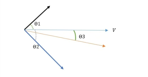
Figure 3. Phasor diagram illustrating the addition of an overexcited synchronous condenser to a lagging load.
While both capacitor banks and synchronous condensers serve similar purposes, they are typically used in different applications. Capacitor banks are more common in industrial settings and smaller substations, while synchronous condensers are better suited for high-power applications, such as power stations exceeding 200 MVA and HVDC converter stations.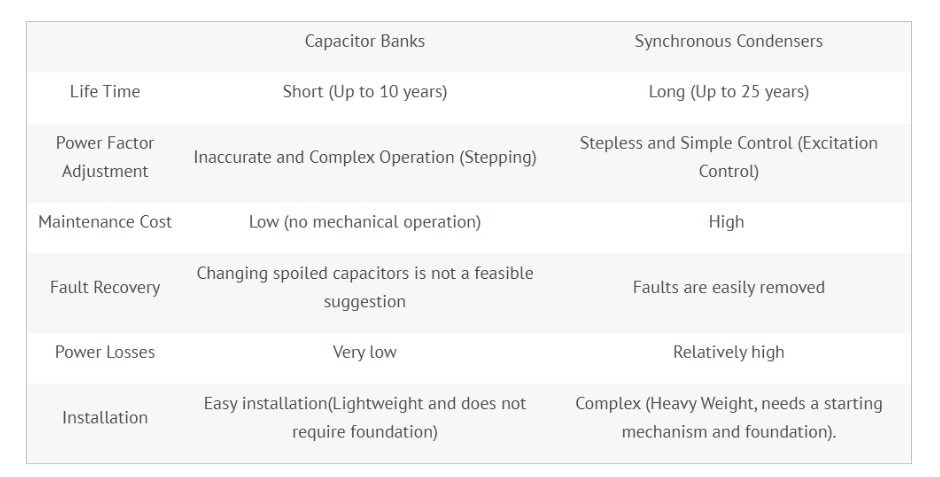


 IPv6 network supported