

 English
 français
 Deutsch
 español
 العربية
 中文
中文
Active Harmonic Filter Sizing: What Happens When You Get It Wrong
Learn how harmonic current, load cycles, topology, temperature, and SVG/AHF selection affect THDi performance.
Consider a textile mill with dozens of VFD-driven spinning frames. A 100 A active harmonic filter (AHF) is installed, but THDi at the PCC falls only from 28% to 19%. The unit is operating normally; it is simply too small for the measured peak harmonic current.
This is a common commissioning lesson: partial capacity produces partial correction.
During ramp-up, harmonic current can exceed the continuous rating of the AHF. Once the module reaches its current limit, the remaining 5th, 7th, and higher-order currents continue upstream to the transformer. The correct rating must therefore come from measured harmonic current across the operating cycle, not from transformer kVA alone.
The gap between datasheet expectations and field performance often begins with sizing assumptions that do not represent actual production conditions.
A common shortcut is to size an AHF as a fixed percentage of transformer kVA. That may provide an initial estimate, but it does not capture load diversity, harmonic spectrum, background distortion, crest factor, or future expansion.
A 2000kVA transformer feeding six-pulse VFDs — the harmonic current follows the drive loading, not the transformer rating. If those drives run at 60% average load with frequent ramp cycles, the harmonic spectrum shifts. Fifth harmonic might hit 33% of fundamental. Seventh, another 12%. These add in RMS, not straight arithmetic.
Background voltage distortion is another factor. If distortion is already present at the PCC, the control and thermal duty of the AHF may differ from a system supplied by a clean voltage waveform. Measure both voltage and current harmonics before final selection.
Three traps that rule-of-thumb sizing walks right into:
|
Comparison |
Passive Harmonic Filter |
Active Harmonic Filter (3-Level Topology) |
|
Compensation method |
Fixed LC tuned circuit targeting specific harmonic orders |
IGBT PWM inverter injecting equal-but-opposite current across full spectrum |
|
Response to load changes |
Static — performance drops when load profile shifts |
Dynamic, real-time tracking, full response under 10ms |
|
Resonance risk |
High — forms parallel resonance points with system impedance |
Low — actively dampens resonance instead of creating new ones |
|
Physical footprint |
Large inductors and capacitors, typically 2-3x AHF volume |
Compact power modules, wall-mount options available |
|
Light load behavior |
Overcompensation risk below 50% load |
Holds setpoint from 10% to 110% rated current |
|
THDi reduction |
Typically brings baseline down to 12-15% |
Maintains <5% THDi at PCC under full load |
These factors are especially important when a utility or project specification requires THDi or TDD performance at the PCC. Passive filtering alone may not maintain the target when the load profile changes.
SVG and AHF are sometimes compared as competing solutions, but they address different primary problems and should be selected from different measurements.
SVG compensates fundamental reactive power. It corrects displacement power factor. It holds voltage steady during motor starts and load swings. The control loop locks onto the fundamental voltage phase angle and synthesizes reactive current accordingly.
AHF compensates harmonic current. It doesn't care about power factor at 50 or 60Hz. It cares about 250Hz, 350Hz, 550Hz — every integer multiple of the fundamental where rectifier loads push distortion back into the grid.
The term "hybrid unit" can describe different architectures. Confirm whether reactive-power and harmonic compensation operate simultaneously, how the inverter current is prioritized, and how performance changes at high ambient temperature or full load.
|
Site type |
Main problem |
Configuration |
Sizing logic |
|
Textile mill, 30+ VFDs |
High THDi (25-40%), moderate displacement PF (0.75-0.85) |
AHF primary, fixed capacitor bank for base reactive |
Size AHF for measured peak harmonic current + 25% margin. Use 3-level topology if heat is tight |
|
Automotive welding line |
Severe harmonic spikes, voltage flicker, PF drops toward 0.6 during weld cycles |
Hybrid AHF+SVG, shared DC bus |
AHF sized for harmonic peaks. SVG sized for max reactive swing over one full production cycle |
|
Data center, UPS + cooling VFDs |
Neutral overload, THDi 15-20%, PF already >0.95 from UPS |
4-wire AHF |
Size for measured neutral current, not phase current. 3rd harmonic dominates |
|
Mining conveyor, soft starters |
Voltage sag on motor start, low PF under light load, moderate harmonics |
SVG primary, passive filter for 5th harmonic |
SVG sized for starting kvar demand. Passive filter for steady-state harmonic load only |
|
Steel EAF feeder substation |
Voltage flicker, severe reactive swing, arc harmonic injection |
MV STATCOM or LV SVG bank |
Size for flicker reduction target. Load study needs 1ms sampling resolution |
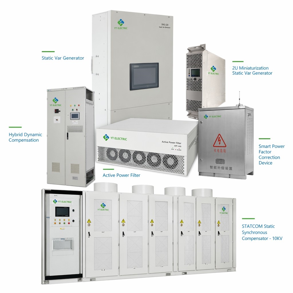
Products for power quality solutions
Semiconductor and module ratings depend on defined thermal conditions. Real electrical rooms may operate at 40-50 C, so the complete equipment derating curve matters more than a single nameplate current.
As ambient and junction temperatures rise, available continuous current may fall. Check the manufacturer's derating curve, enclosure ventilation, altitude, dust loading, and the temperature measured at the actual installation location.
A three-level topology divides the DC-bus voltage across additional switching states, reducing voltage stress per device and supporting a lower-ripple output waveform. The practical thermal benefit depends on the semiconductor, switching frequency, cooling design, and control strategy.
In Southeast Asia, the Middle East, and other hot-climate installations, thermal margin is a core selection criterion. A filter must maintain the required output during the hottest production period without repeated overtemperature derating or trips.
Recommended practice: measure the temperature at the proposed panel location. If it exceeds 35 C, use the manufacturer's high-ambient derating data and consider a three-level or enhanced-cooling design.
A practical way to reduce undersizing risk is to log power quality for at least 72 hours before final selection. Longer monitoring may be required for seasonal or batch loads.
The logging window should cover a representative production cycle: startup, ramp, steady state, and shutdown. For intermittent loads such as welding, include the worst-case operating schedule. Light-load measurements alone may miss the peak harmonic current.
The data tells you straight:
· Actual THDi at each load step
· Which harmonic orders dominate — not all filters handle all orders equally
· Background voltage distortion coming in from the grid
· Reactive swing magnitude and speed
· Neutral current — often the single number that decides 3-wire versus 4-wire AHF
Without measured data, selection remains an estimate. A site audit provides the information needed to size a system that performs at full production load and the actual room temperature.
Q: Can I install an AHF without shutting down the plant?
A: The AHF connects in parallel, but CT installation and feeder work may require isolation of the monitored bus. Plan the outage scope with the site electrical team and follow the approved safety procedure.
Q: My load changes with the seasons. How should I size the AHF?
A: Use the worst representative harmonic-current measurement and include an agreed design margin. For short seasonal peaks, a modular system can provide a practical expansion path.
Q: What maintenance does a three-level AHF need?
A: Follow the product manual. Typical tasks include cleaning filters, inspecting fans and terminals, reviewing alarms and temperature records, and verifying compensation performance. The interval depends on dust, ambient temperature, and operating hours.
Q: Can an SVG operate with existing capacitor banks?
A: Yes, when the controls are coordinated. The capacitor bank can carry base reactive demand while the SVG handles rapid changes. Confirm switching thresholds, detuning, CT location, and the target power factor to avoid hunting or overcompensation.
Explore YT Electric product specifications and application guidance: https://www.ytelect.com/blog/guide-to-selecting-active-harmonic-filters_b321
Reference: IEEE 519-2022, IEEE Standard for Harmonic Control in Electric Power Systems: https://standards.ieee.org/ieee/519/10677/
Need a site-specific solution? Share your single-line diagram, load list, measured power factor, THDi/TDD data, and ambient conditions with YT Electric. Our sales engineers can review the data and prepare a technical proposal.



 IPv6 network supported