

 English
 français
 Deutsch
 español
 العربية
 中文

Industrial plants, manufacturing complexes, and large commercial facilities frequently face a challenging power quality engineering dilemma: utility metering occurs on the medium-voltage (MV) intake bus (such as 6.6 kV, 10 kV, 13.8 kV, or 35 kV), while the vast majority of non-linear and inductive loads operate on the low-voltage (LV) 400V, 480V, or 690V secondary systems. When plant operators attempt to correct poor power factor (PF) and eliminate utility penalty billing, they are often told that only an expensive, bulky medium-voltage STATCOM or MV capacitor bank can solve the problem at the billing meter.
However, modern power electronics provide a vastly superior, cost-effective alternative: Medium-Voltage Sensing with Low-Voltage Compensation. By deploying high-precision MV Current Transformers (CTs) paired with a fast-acting low-voltage Static Var Generator (SVG), plant engineers can achieve a perfect 0.99+ power factor at the primary utility meter while slashing capital expenditure (CAPEX) by 40% to 60% compared to high-voltage equipment.
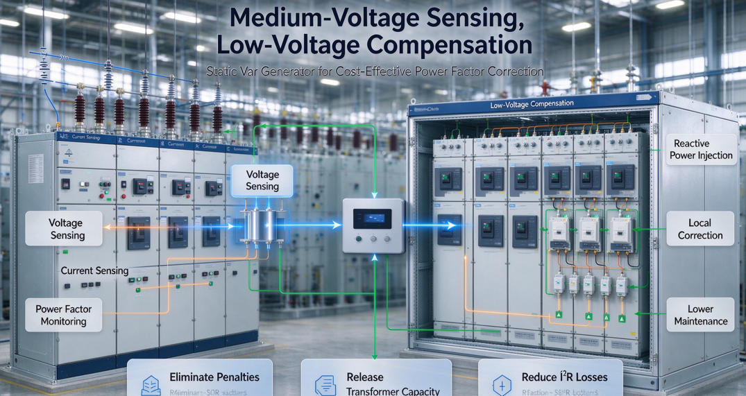
Figure 1: Medium-Voltage Sensing with Low-Voltage Dynamic SVG Compensation Topology
Direct medium-voltage reactive compensation hardware introduces severe engineering, financial, and spatial constraints for facility operators:
The MV-Sensing / LV-Compensation topology operates on a simple yet mathematically precise principle: measure power quality where the utility calculates billing (the MV PCC), but inject compensating currents directly where power is consumed (the LV busbars).
High-accuracy medium-voltage current transformers (typically class 0.2S or 0.5S) are installed at the primary incoming switchgear. The secondary CT signals are transmitted directly to the central digital signal processor (DSP) controller of the low-voltage Static Var Generator (SVG) or integrated Active Harmonic Filter (AHF) system.
The SVG's internal control algorithm continuously calculates two critical variables in real time:
By dynamically compensating both the LV load vars and the transformer's own reactive impedance losses from the secondary side, the SVG ensures that the primary utility meter sees near-unity power factor (cos φ ≥ 0.995) at all times.
| Architecture Feature | Direct MV STATCOM | Standard LV APFC (LV Sensing) | YT Electric MV Sensing + LV SVG |
|---|---|---|---|
| System Equipment Cost | Very High (100% Benchmark) | Low (25% - 30%) | Optimal (35% - 45% of MV STATCOM) |
| MV Meter Power Factor | Accurate 0.99+ | Sub-optimal (Ignores Transformer XL) | Guaranteed 0.995+ at MV Meter |
| Transformer Thermal Relief | Zero relief (Transformer carries vars) | Partial relief (Stepped) | Maximum (Frees 15-25% kVA capacity) |
| Installation Space / Footprint | Large MV switchgear room required | Standard floor-standing cabinets | Compact modular rack/wall cabinets |
| Response Speed | < 10 ms | 5 - 20 seconds (Slow contactors) | < 5 ms (Stepless IGBT modulation) |
| Maintenance & Safety Level | High-voltage hazard, certified crew | Frequent capacitor replacement | Safe low-voltage plug-and-play modules |
When sizing a low-voltage SVG to achieve compliance at a medium-voltage utility meter, engineers must incorporate both the load reactive demand and the transformer impedance losses (%Z). The selection guide below illustrates standard sizing across common industrial distribution transformers:
| Transformer Rating | Primary / Secondary Voltage | Impedance (%Z) | Transformer Reactive Loss (Full Load) | Recommended LV SVG Capacity |
|---|---|---|---|---|
| 800 kVA | 10 kV / 400V (or 13.8kV / 480V) | 4.5% - 5.0% | ~38 kvar - 42 kvar | 200 kvar - 250 kvar |
| 1250 kVA | 10 kV / 400V (or 13.8kV / 480V) | 5.0% - 6.0% | ~65 kvar - 75 kvar | 300 kvar - 400 kvar |
| 2000 kVA | 10 kV / 400V (or 35kV / 400V) | 6.0% - 7.0% | ~120 kvar - 140 kvar | 500 kvar - 600 kvar |
| 3150 kVA | 35 kV / 400V (or 22kV / 690V) | 7.0% - 8.0% | ~220 kvar - 250 kvar | 800 kvar - 1000 kvar (Multi-module) |
Yes. Because the SVG controller samples currents directly from the medium-voltage utility intake CTs, it treats the transformer and the low-voltage plant as a single integrated electrical block. It automatically compensates for both the load vars and the transformer's internal reactive losses, ensuring the MV meter records a compliant 0.995+ power factor.
Standard medium-voltage measurement CTs with a secondary output of 5A or 1A and an accuracy class of 0.5S or 0.2S are fully compatible. Shielded twisted-pair cabling is used to route CT secondary wiring from the MV switchgear to the SVG controller panel.
In multi-transformer substations, YT Electric SVG systems utilize master-slave communication architecture or summation CT inputs. The master controller monitors the total MV incoming feeder and dynamically allocates compensation duties across the distributed LV SVG units on each transformer bus.
No. The modular SVG units connect to standard low-voltage feeder breakers. CT installation in the MV switchgear can be scheduled during standard annual maintenance windows or performed using split-core current sensors where permitted.
Discover how YT Electric MV-Sensing Low-Voltage SVG solutions can eliminate utility power factor penalties and increase your plant's transformer capacity. Contact our application engineering team today for a comprehensive Single-Line Diagram (SLD) review.



 IPv6 network supported