

 English
 français
 Deutsch
 español
 العربية
 中文

Utility-scale and distributed solar photovoltaic (PV) plant operators worldwide face escalating monthly utility penalties for power factor (PF) non-compliance at the Point of Common Coupling (PCC). While solar farm developers engineer their systems for maximum active power generation during peak irradiance, grid codes such as IEEE 1547, IEEE 2800, and ENTSO-E mandate strict reactive power exchange boundaries across the entire 24-hour cycle. When cloud cover causes sudden generation drops, or during nighttime when inverters idle, solar installations frequently violate grid PF thresholds, incurring severe financial penalties from transmission system operators (TSOs) and regional utilities.
Deploying a dedicated Static Var Generator (SVG) offers an ultra-fast, dynamic reactive power compensation architecture that eliminates power factor penalties, stabilizes PCC voltage, and prevents costly inverter active power curtailment.
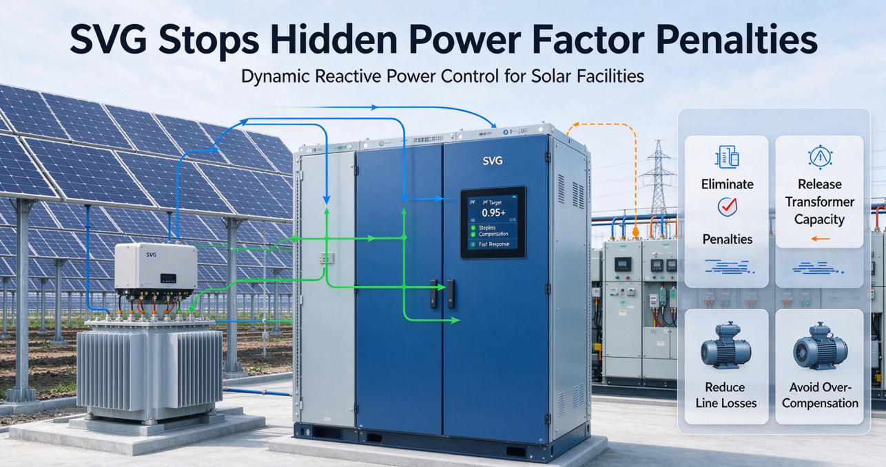
Figure 1: High-Speed Static Var Generator (SVG) Dynamic Grid Support for Solar PV Farms
A solar power plant is not a passive electrical system. Even when inverters produce zero active megawatts at night, the balance-of-plant (BOP) infrastructure actively consumes and generates reactive power:
Historically, solar engineers attempted to resolve PF issues using stepped capacitor banks (APFC) or by de-rating inverter active power capacity to deliver reactive vars. Both approaches carry crippling operational liabilities:
Automatic Power Factor Correction (APFC) capacitor banks operate with electromechanical contactors or basic thyristor switches. Their response time ranges between 5 and 30 seconds—far too sluggish to track cloud transients. Furthermore, stepped capacitor banks provide discrete, stepped compensation rather than smooth, stepless output, creating continuous over-compensation and under-compensation cycles. In severe cases, fixed capacitor banks form harmonic resonances with transformer leakage inductances and inverter output filters, magnifying Active Harmonic Filter (AHF) mitigation requirements.
Conversely, reserving inverter headroom for reactive power (operating at 0.90 or 0.95 PF during peak midday sun) forces operators to curtail lucrative active power feed-in. Sacrificing active energy revenue to provide grid support represents a severe economic penalty over the 25-year asset lifecycle.
| Parameter / Feature | Stepped APFC Banks | Inverter Q-at-Night | YT Electric Dynamic SVG |
|---|---|---|---|
| Response Speed | 5 - 30 seconds | 100 - 500 milliseconds | < 5 milliseconds (<15ms full step) |
| Compensation Mode | Capacitive only (Stepped) | Bidirectional (Continuous) | Bidirectional (Stepless ±1.0 to 0.00 PF) |
| Impact on Active Revenue | Zero revenue loss | 10% - 15% generation curtailment | Zero curtailment (100% active MW exported) |
| Grid Voltage Sensitivity | Output drops with V2 (Impedance) | Moderate voltage support | Current source behavior (Linear with V) |
| Harmonic Resonance Risk | High risk with MV transformers | Low risk | Zero resonance risk (Active IGBT bridge) |
| Equipment Lifespan | 3 - 5 years (Capacitor wear) | Reduces inverter MTBF | > 100,000 operating hours |
A Static Var Generator operates as a self-commutated, voltage-source converter (VSC) based on high-frequency Insulated Gate Bipolar Transistors (IGBTs) switching at 25.6 kHz. By continuously sampling line voltage and load currents via high-precision current transformers (CTs), the internal DSP digital controller calculates the exact instantaneous reactive power deficit required at the utility meter.
When the grid requires inductive compensation (such as when overcoming nighttime underground cable capacitance), the SVG modulates its internal AC voltage to lag the grid voltage, dynamically absorbing vars. When the plant demands capacitive support (such as during full generation through inductive step-up transformers), the SVG leads the grid voltage, instantly injecting clean capacitive reactive current. The entire compensation response occurs within 5 milliseconds, guaranteeing a constant 0.99 to 1.00 power factor at the billing meter under all weather and irradiance conditions.
Selecting the correct SVG capacity requires sizing for both peak solar generation losses (inductive var demand) and nighttime cable charging (capacitive var absorption). The engineering matrix below outlines standard SVG capacity recommendations across common solar farm capacities:
| Solar Plant Capacity | Grid Interconnection Voltage | Typical Cable Length & Type | Recommended SVG Rating | Optimal System Topology |
|---|---|---|---|---|
| 1 MW - 3 MW (C&I Rooftop) | 400V / 480V LV Bus | Short LV Busway (<200m) | 150 k专项 - 300 kvar | Wall-mount / Rack Modular LV SVG |
| 5 MW - 10 MW (Distributed Solar) | 10 kV / 13.8 kV / 22 kV | 2 km - 5 km XLPE Medium Voltage | 500 kvar - 1000 kvar | LV Centralized SVG via dedicated secondary bus |
| 20 MW - 50 MW (Utility Solar) | 33 kV / 34.5 kV Collection | 10 km - 25 km MV Cables | 2 Mvar - 5 Mvar | Containerized Hybrid SVG / MV STATCOM |
| 100 MW+ (Mega-Solar Hub) | 66 kV / 110 kV / 220 kV Substation | Extensive collection network | 10 Mvar - 25 Mvar | Medium-Voltage Cascaded Multilevel STATCOM |
A 15 MW solar facility operating across an arid desert terrain experienced recurring monthly utility penalties exceeding $14,000 for nighttime leading power factor (PF 0.82 capacitive) caused by 8.5 km of 33 kV underground collection cables. Furthermore, severe cloud ramp transients during afternoon convective storms triggered frequent PCC overvoltage tripping events.
The plant engineering team integrated a 1,200 kvar YT Electric modular Static Var Generator (SVG) configured on the substation auxiliary low-voltage bus with medium-voltage sensing. Within 48 hours of commissioning:
While inverters can provide reactive power, doing so during peak generation hours requires de-rating active power exports, directly sacrificing electricity feed-in revenue. Additionally, running inverters continuously at night for "Q-at-Night" accelerates IGBT wear and increases auxiliary power consumption. A dedicated SVG decouples reactive power compliance from energy production, maximizing plant profitability.
At night, solar plant cables act as large capacitors, injecting leading vars into the utility grid. An SVG dynamically detects this capacitive excess and generates an exact equivalent inductive reactive current, neutralizing the cable capacitance at the PCC and maintaining a compliant unity power factor.
YT Electric Static Var Generators achieve an ultra-fast full-response time of under 5 milliseconds. This allows the system to seamlessly track lightning-fast irradiance drops and cloud transitions without hunting, overshooting, or triggering grid protection relays.
Yes. YT Electric manufactures both modular indoor rack-mounted units and fully packaged outdoor IP54/IP55 containerized solutions equipped with intelligent HVAC cooling, seismic dampening, and integrated SCADA communication gateways (Modbus TCP, IEC 61850).
Stop losing revenue to utility power factor charges. Contact our senior power quality engineering team today to review your solar farm single-line diagrams (SLD) and receive a tailored, high-performance SVG sizing proposal.



 IPv6 network supported