

 English
 français
 Deutsch
 español
 العربية
 中文

How to Reduce Harmonic Distortion in VFD Systems
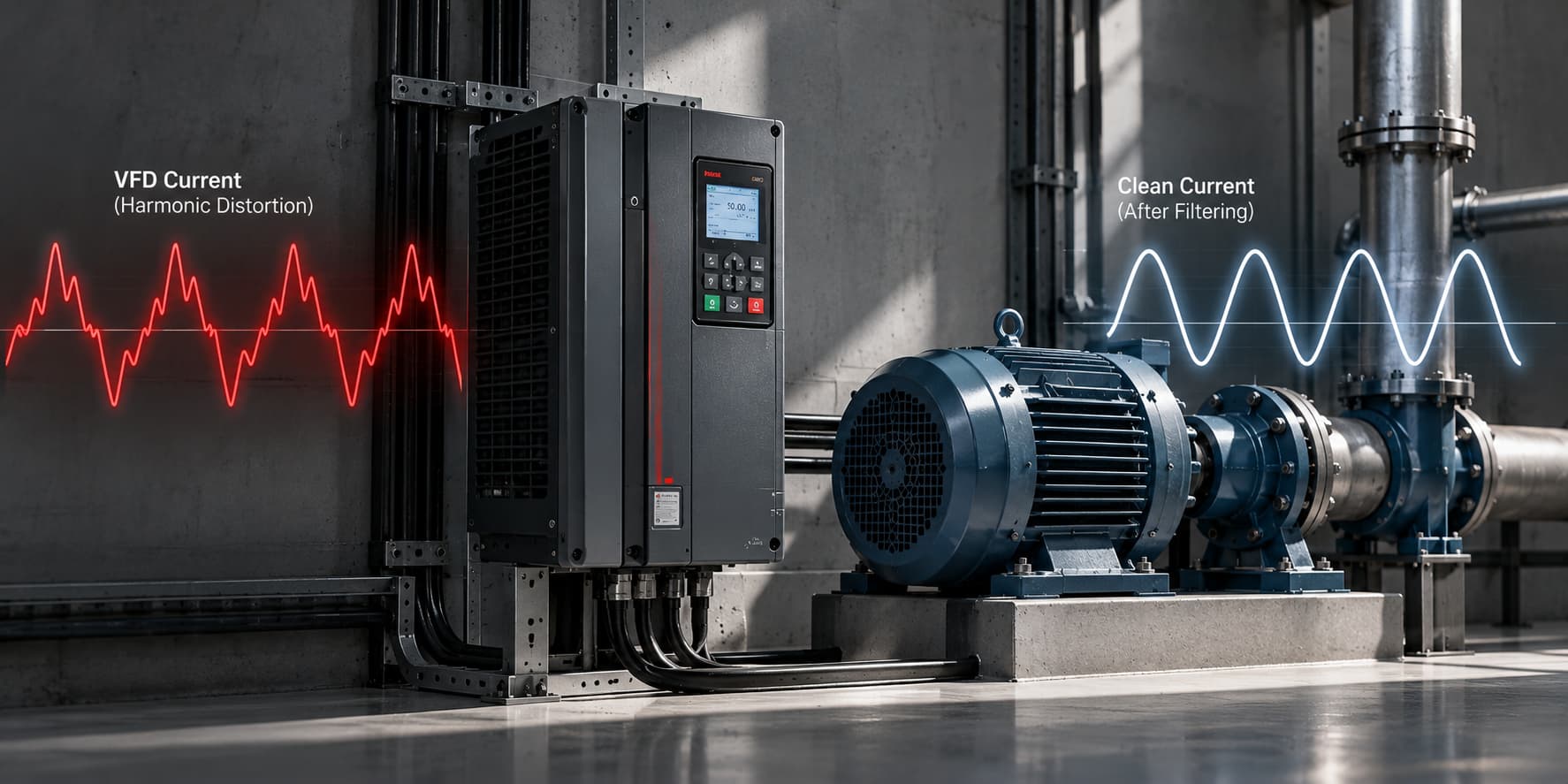
Variable Frequency Drives (VFDs) help factories control motor speed and reduce energy consumption. However, they can also introduce harmonic distortion into the electrical network. When several drives operate together, these harmonics can increase transformer heating, overload cables, and affect sensitive equipment.
Reducing harmonic distortion in VFDs starts with understanding how drives generate harmonics, measuring the actual distortion, and selecting the correct filtering method. This guide explains the causes, risks, and practical solutions for industrial power systems.
Most standard VFDs use a rectifier to convert incoming AC power into DC power. An inverter then converts the DC voltage into variable-frequency AC power to control the motor.
The problem begins at the rectifier. A typical six-pulse VFD draws current in short pulses instead of a smooth sine wave. This creates harmonic currents that flow back into the electrical supply.
The most common harmonics produced by six-pulse drives are the 5th, 7th, 11th, and 13th orders. Their magnitude depends on the drive design, supply impedance, and operating conditions.
As more VFDs are installed, the combined harmonic current can become a serious power quality problem.
Harmonic distortion affects more than the drives themselves. It can increase electrical losses and place additional stress on equipment connected to the same network.
Common problems include:
Transformer overheating: Harmonic currents increase winding and stray losses.
Capacitor bank failures: Harmonics can cause excessive current, especially near resonance conditions.
Cable heating: Higher RMS current increases conductor losses.
Breaker trips: Distorted currents may contribute to protection problems.
Voltage distortion: Harmonic currents flowing through system impedance distort the supply voltage.
These effects depend on harmonic levels and the electrical system design. A high THDi reading does not automatically mean equipment damage, but it signals the need for further investigation.
Before installing a filter, engineers should measure harmonic distortion using a power quality analyzer.
The analyzer should record the fundamental current, individual harmonic currents, total harmonic distortion, and voltage distortion. Measurements should cover normal production and peak operating conditions.
Two important values are:
THDi: Total Harmonic Distortion of current, expressed as a percentage of the fundamental current.
THDv: Total Harmonic Distortion of voltage, expressed as a percentage of the fundamental voltage.
For example, a VFD feeder with 200 A fundamental current and 35% THDi carries approximately 70 A of combined harmonic current.
This measurement helps engineers determine the amount of compensation needed.
Several technologies can reduce harmonic distortion. The best choice depends on the number of drives, their operating patterns, and the required harmonic limits.
|
Solution |
How it works |
Best application |
|---|---|---|
|
AC line reactor |
Adds impedance to reduce current peaks |
Individual VFDs |
|
DC link choke |
Smooths current in the DC circuit |
Drives with compatible designs |
|
Passive harmonic filter |
Uses tuned electrical components to reduce selected harmonics |
Relatively stable loads |
|
Injects compensating harmonic current |
Multiple VFDs and changing loads |
|
|
Low-harmonic or active-front-end drive |
Uses an improved input stage to reduce harmonics |
New installations with strict limits |
AC line reactors are among the simplest ways to reduce harmonic distortion in VFDs.
They limit the sharp current pulses drawn by the rectifier. A commonly used reactor impedance is around 3%, although the correct value depends on the drive and system.
Line reactors reduce harmonic current but do not eliminate it. They are often suitable when moderate harmonic reduction is sufficient.
DC link chokes help smooth the current inside the VFD.
They can reduce input harmonic distortion without requiring a separate external filter. However, their effectiveness depends on the drive design and operating conditions.
Not every VFD supports an external DC choke, so compatibility must be checked.
Passive filters use inductors and capacitors to reduce selected harmonic frequencies.
They can provide effective harmonic reduction when loads remain relatively stable. However, their performance depends on system impedance and operating conditions.
Engineers must also consider resonance risks before installing passive filters.
An Active Harmonic Filter measures harmonic current and injects an opposing current to compensate for distortion.
Unlike passive filters, an AHF can adjust its output as VFD loading changes. This makes it useful for factories with multiple drives operating at different speeds.
A correctly sized AHF can reduce harmonic distortion significantly. However, the final result depends on the harmonic spectrum, available filter capacity, and installation conditions.
For new installations, low-harmonic VFDs or active-front-end drives may offer another solution.
These drives use input technologies designed to reduce harmonic current. They can be effective where strict harmonic performance is required.
However, their higher initial cost should be compared with external filtering solutions.
Correct filter sizing starts with measured harmonic current, not motor power alone.
The basic calculation is:
Where:
\(I_H\) = total harmonic current
\(I_1\) = fundamental current
THDi = current harmonic distortion percentage
Consider a manufacturing plant with a fundamental feeder current of 400 A and measured THDi of 30%.
The harmonic current is:
The system therefore carries approximately 120 A of combined harmonic current.
A filter rated around 120 A could theoretically compensate that current under the measured conditions. However, the final selection must account for the target distortion, harmonic spectrum, peak loading, and future expansion.
For accurate sizing, engineers should review the manufacturer's compensation specifications and the complete power quality measurements.
IEEE 519 provides recommended limits for harmonic distortion at the Point of Common Coupling (PCC).
One common mistake is assuming that every VFD must achieve less than 5% THDi.
In reality, IEEE 519 evaluates current distortion using Total Demand Distortion (TDD). The applicable limits depend on the ratio between available short-circuit current and maximum demand load current at the PCC.
Voltage distortion limits are also considered.
Therefore, achieving IEEE 519 compliance requires measurements at the correct location, not simply checking the THDi displayed on a VFD.
Several mistakes can reduce the effectiveness of a harmonic mitigation project.
The first is selecting a filter using only the VFD's rated current. Harmonic current changes with drive loading and input design.
Another mistake is measuring distortion when production is running at low capacity. The results may not represent peak operating conditions.
Engineers should also avoid installing capacitor banks without checking harmonic resonance. Capacitors can interact with network inductance and amplify certain harmonic currents.
Finally, installing an AHF at the wrong location may leave parts of the electrical network exposed to unwanted harmonic currents.
Standard six-pulse VFDs commonly produce 5th, 7th, 11th, and 13th harmonic currents. Their actual levels depend on the drive and electrical system.
Yes, this may be achievable with correct sizing and installation. However, performance depends on the existing distortion, operating conditions, and filter capability.
No. The need for filtering depends on measured distortion, system strength, equipment sensitivity, and applicable requirements.
Line reactors can provide useful harmonic reduction, but they may not achieve strict distortion targets. Additional filtering may be necessary.
An AHF can be installed at a main distribution board or near a group of VFDs. The best location depends on the harmonic sources and the point where compensation is required.
Reducing harmonic distortion in VFDs requires more than installing a filter. Engineers must first measure harmonic current, identify the main sources, and understand the required performance.
Line reactors and DC chokes offer practical solutions for moderate distortion. Passive filters work well in suitable stable-load applications, while Active Harmonic Filters provide flexible compensation for changing industrial loads.
For facilities operating multiple VFDs, proper measurement and filter sizing can reduce electrical stress, improve reliability, and support IEEE 519 compliance.



 IPv6 network supported