

 English
 français
 Deutsch
 español
 العربية
 中文

An APFC panel is not simply permitted or forbidden on generator power. Compatibility depends on generator capacity, the power factor of the load that stays online, the size of each load step, harmonic distortion, available short-circuit capacity, governor and excitation response, the generator manufacturer’s limits, and the logic inside the APFC controller. On many standby systems the recommended practice is to inhibit or disconnect fixed and automatically switched capacitor steps whenever the generator is the source, and to re-verify every setting for island operation rather than reusing utility defaults.
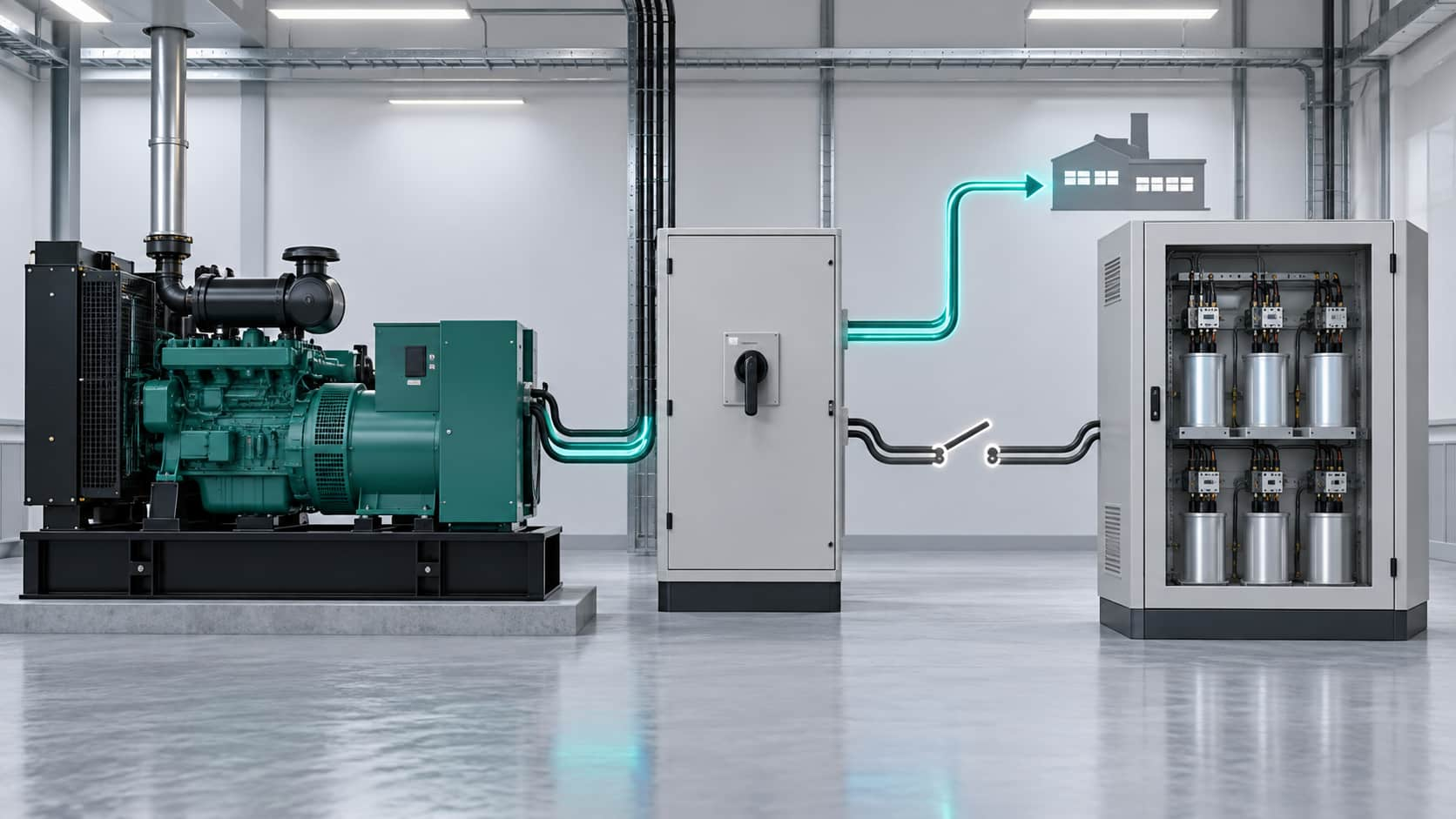
The utility network is a stiff, high-capacity source, while a standby generator is a limited source, and that single difference reshapes the reactive-power picture. When the transfer switch opens and the generator picks up the load, source impedance rises, short-circuit current falls, voltage is governed by the excitation system rather than an infinite bus, and the connected load is usually smaller and less predictable than normal plant demand. Table 1 summarises the main shifts and why each matters.
Table 1 – How the electrical environment changes on generator supply
| Parameter | On utility supply | On a standby generator | Why it matters for APFC |
|---|---|---|---|
| Source strength | Very high, near-infinite bus | Limited by alternator kVA and subtransient reactance | Reactive steps cause larger voltage changes |
| Short-circuit capacity | High and stable | Low, varies with connected load | Weak source amplifies resonance and step effects |
| Voltage regulation | Grid holds voltage | AVR and excitation respond with delay | Slow response can allow overvoltage or hunting |
| Frequency control | Governed by the grid | Governor reacts to load steps | Repeated capacitor steps add to load-step stress |
| Connected load | Full plant demand | Emergency or essential loads only | Utility-sized steps can overcompensate |
| Harmonic environment | Damped by a strong grid | More sensitive to VFD, UPS and rectifier loads | Capacitors can amplify voltage distortion |
An APFC panel that behaves perfectly on utility supply can therefore become unstable on generator supply. The practical question is not only whether the panel can run, but whether it should be allowed to switch capacitor steps at all.
When fixed or automatically switched capacitors remain connected in island mode, a group of related risks appears. Each is manageable, but only if it is identified before the next outage.
Harmonic effects are frequently underestimated. Where distortion is significant, a dedicated active power filter can be coordinated with the compensation scheme so the generator is not asked to absorb harmonic current it was never sized for.
If the generator manufacturer permits any power-factor correction during island operation, the controller must be re-commissioned for generator mode; utility defaults cannot be assumed valid. At a minimum these parameters need to be re-verified against the generator datasheet and a measured load profile:
A static var generator (SVG) responds continuously and can both inject and absorb reactive power, so it is often more flexible than stepped capacitors on a weak source. Correcting smoothly rather than in discrete steps reduces coarse reactive jumps, helps hold voltage and power factor during load swings, and can avoid the leading-power-factor region that damages capacitor-based schemes. A static var generator is therefore frequently chosen where the generator must run with variable emergency loads.
SVG flexibility does not remove the engineering work. Generator capacity, short-circuit and stability verification, and protection coordination still have to be completed, and the device must be sized correctly — the same discipline that applies to SVG sizing for power factor correction on utility supply. Many users compare the options and ask when an APFC panel is enough; under generator operation the dynamic option usually needs less re-configuration but a stricter system review.
Before the next outage, work through the following items with the generator vendor and the panel designer:
Table 2 relates common generator operating conditions to the risk of leaving capacitor steps engaged and to the control action that should be considered.
Table 2 – Generator-mode safety and control matrix
| Operating condition | Risk if capacitors stay engaged | Recommended control action | What to verify |
|---|---|---|---|
| Generator at light load | Leading power factor, overvoltage, possible trip | Inhibit or disconnect all steps | Light-load reactive balance and AVR margin |
| Large motor starting | Step plus motor inrush, voltage dip then rise | Block step switching during starts; sequence loads | Largest step change and voltage recovery |
| Transfer to generator | Utility-mode steps left connected | Open capacitor steps before transfer | Interlock timing and discharge time |
| Re-transfer to utility | Residual voltage and re-close surge | Delay re-enable until generator off and steps discharged | Discharge timer and re-close logic |
| Nonlinear loads online | Harmonic resonance and voltage distortion | Keep capacitance minimal; consider filtering | Harmonic spectrum and resonance points |
| Islanded operation with approved correction | Control hunting if settings are wrong | Run with re-commissioned settings and monitoring | Target PF, delays, step size and CT signal |
Not without checking both manufacturers’ instructions. Many installations require a generator-mode inhibit or a disconnection of the capacitor steps. Automatic operation should continue only if the generator vendor has approved it and the settings have been re-verified for island operation.
Not always. Utility power-factor penalties do not apply during generator operation, but generator capacity, voltage and excitation limits still matter. Correction should be added only if the design and the generator vendor permit it.
No. Detuning addresses one specific resonance risk. It does not by itself prevent overcompensation, reverse kVAr, overvoltage or an unsuitable capacitor-switching sequence.
No. An SVG is more flexible and avoids coarse steps, but its compatibility with the alternator, AVR and connected load still has to be studied. It replaces neither the generator capacity check nor the protection study.
An APFC panel that performs well on utility power should not automatically keep switching capacitor steps when the generator is the source. Emergency loads, harmonics and generator capability all differ from normal service, and the risks of overcompensation, overvoltage, resonance and control instability are real. Confirm the manufacturer’s limits, verify the transfer interlock, re-commission the controller for generator mode, and measure the system at the point of common coupling before committing to a scheme.
YT Electric can review your APFC panel, generator data and transfer sequence, and help identify a power-factor correction arrangement that is safe for both normal and backup operation.



 IPv6 network supported