

 English
 français
 Deutsch
 español
 العربية
 中文

A fixed capacitor bank is often the most economical way to correct power factor — provided the load stays reasonably steady. When motors cycle or production changes by shift, it may overcompensate overnight and undercompensate at peak. An Automatic Power Factor Correction (APFC) panel switches capacitor steps as demand changes; a Static Var Generator (SVG) adjusts reactive power continuously and responds within milliseconds.
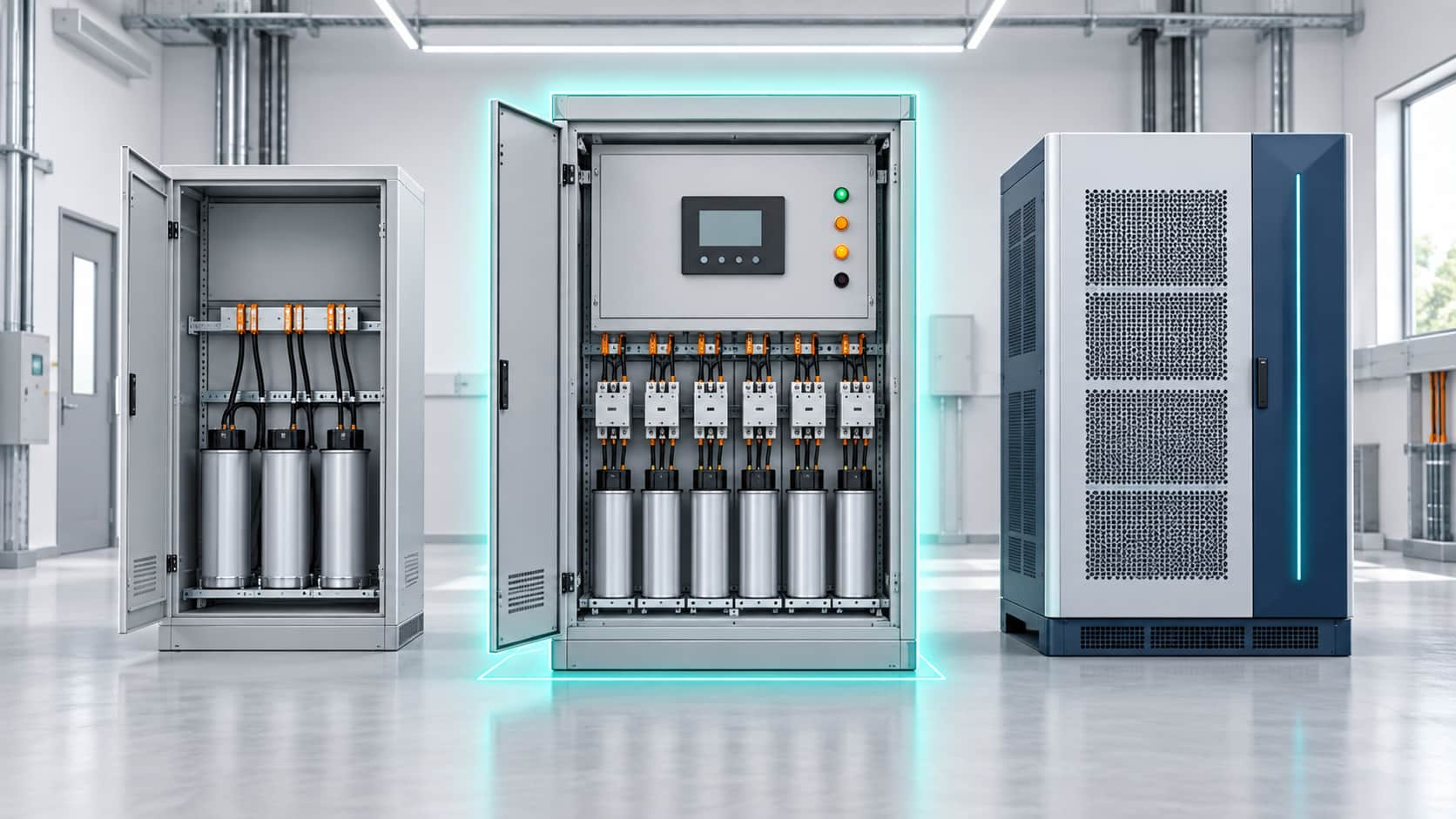
The practical question is not which technology is “best”, but when an APFC panel is enough — and when the extra capability of an SVG, or a dedicated harmonic filter, is genuinely required. This guide compares the three approaches, the load patterns that decide the answer, and the harmonic, resonance, and current-transformer issues that are easy to overlook. Final capacity and configuration should be confirmed against on-site measurement rather than assumed from nameplate data.
An APFC panel is usually sufficient when reactive demand is dominated by a lagging (inductive) power factor, when the load changes gradually across shifts, and when the correction can be reached with a practical number of capacitor steps. It is a strong candidate where a fixed bank has proven too coarse — overcompensating at light load or falling short at peak.
A fixed capacitor bank supplies approximately the same reactive power whenever it is connected — no controller, no current transformer, no switching stages. Because the compensation does not change, it suits a nearly constant inductive load, such as a single large motor at steady output. Its weakness appears at light load: the capacitors stay connected and can push the installation into a leading power factor, which utilities may penalise as heavily as a lagging one.
An APFC panel is essentially a capacitor bank with a controller, a current transformer, switching devices (contactors or thyristors), protection, and several capacitor steps. The controller reads the measured power factor and connects or disconnects steps to hold the compensated factor close to target. Accuracy depends on the smallest step and on the switching speed: contactor-switched panels are economical but slow, while thyristor-switched panels respond faster while still switching in steps.
An SVG uses power electronics to produce continuously variable reactive power. Instead of selecting fixed steps, it follows the measured requirement and can both supply and absorb capacitive reactive power within its rating. That suits demand changing faster than a switched bank can follow, fine regulation, or a power factor that swings into the leading region. YT Electric builds its static var generator range for exactly these dynamic conditions, and the SVG product platform covers a wide range of capacities.
| Aspect | Fixed Capacitor Bank | APFC Panel | Static Var Generator (SVG) |
|---|---|---|---|
| Correction method | Constant while connected | Switched capacitor steps | Continuous electronic output |
| Load pattern | Nearly constant | Gradual change by shift | Fast or unpredictable |
| Response speed | None | Seconds to milliseconds | Sub-cycle |
| Precision | Fixed amount | Limited by step size | Stepless |
| Leading power factor | Can overcompensate | Cannot absorb reactive power | Can absorb excess |
| Harmonics | Resonance risk | Same risk; detune if needed | No capacitor resonance |
| Initial cost | Lowest | Middle | Highest |
| Footprint | Small | Moderate | Larger |
| Main limitation | Cannot follow load | Step size limits accuracy | Higher investment |
Configuration, detuning, protection, and installation can all change the real cost and performance, so read the table as a guide, not a quotation.
Use the matrix below as a first filter: it maps site conditions to a likely technology and to the point that must be verified before ordering.
| Condition on site | Likely choice | What to confirm |
|---|---|---|
| Constant inductive load, low harmonics | Fixed capacitor bank | Light-load power factor |
| Varies by shift but gradually | APFC panel | Smallest practical step |
| Changes rapidly (cranes, welders) | SVG | Dynamic range and response |
| Swings leading and lagging | SVG | Absorbs capacitive reactive power |
| High harmonic distortion | Detuned APFC or active filter | Resonance points |
| Reduce harmonic current, not PF | Active power filter or hybrid | Harmonic orders |
| Capacity and target PF unknown | Measurement study first | PCC data and CT position |
The single most useful input is the load profile: how active power, reactive power, and power factor change across a full production cycle, including nights, weekends, and seasonal peaks. Two facilities with the same connected load can need very different solutions if one runs at constant output while the other starts and stops large motors throughout the day.
Step-based compensation is limited by its smallest step relative to the load. If that step is large compared with light-load demand, the controller must choose between overcorrecting and undercorrecting, and the measured power factor oscillates around the target. Where the load is smaller and more erratic than the step resolution can handle, a continuously variable solution fits better.
An APFC panel makes a capacitor bank automatic; it does not make capacitors immune to harmonics. Drives, rectifiers, and UPS systems inject harmonic currents, and capacitors can form a resonant circuit with system inductance, amplifying voltage and current distortion near a resonant frequency. Detuned reactors shift the resonance point away from dominant harmonics, but they do not remove harmonic current from the network.
If harmonic current itself must be reduced, capacitor-based equipment is the wrong tool. That task belongs to filtering equipment such as an active power filter, including products such as the Active Power Filter APF. Where compensation and mitigation are both needed, a combined arrangement often performs better than either device alone — a hybrid real-time PFC bank with SVG is one example.
Measure at the point of common coupling (PCC), where the facility connects to the utility network, because that is where power factor is measured and penalised. Measuring deep inside the plant can show a healthy local value while the PCC figure stays poor, especially when transformers or long cable runs contribute reactive losses.
The controller bases its decisions on the current transformer, so the CT must measure the total load to be compensated, on the correct side of the point where compensation is injected. A CT in the wrong position can cause oscillation, overcompensation, or continuous switching. CT ratio, phase, and burden must all match the controller.
A controller target is not delivered performance. Verify the achieved power factor at the PCC under real conditions — at light load as well as at peak, and over a representative period — to confirm that step sizes, switching strategy, and capacity actually hold the target in practice.
An APFC panel can only work with the stages it has. An oversized minimum step causes persistent under- and overcorrection; a load changing faster than the switching devices can react, such as welders or cranes, cannot be ; and capacitor stages cannot absorb capacitive reactive power, so a persistent leading power factor will not be solved by adding stages. These are the situations in which an SVG is usually the better answer. For a worked sizing method against real load data, see SVG sizing for power factor correction.
An APFC panel typically contains a capacitor bank, but adds automatic control, sensing, and switched stages. A fixed bank supplies a constant amount of compensation while connected, whereas an APFC panel changes the connected amount as the load varies.
An automatically switched capacitor bank generally has a lower upfront equipment cost than a full SVG of comparable capacity, but not in every configuration. Detuning, switching equipment, protection, installation, and maintenance all affect the comparison, so both options should be judged against the same measured objective.
No. Its primary function is reactive-power compensation. Detuned reactors can reduce resonance risk, but when harmonic current itself must be reduced, an active harmonic filter is used instead.
Sometimes. The existing capacitors must be suitable for staged switching and their condition verified. The upgrade also needs a correctly located CT, a controller, switching devices, protection, and an assessment of harmonics and practical step sizes.
For a stable inductive load, a fixed capacitor bank may be sufficient. When demand changes across the working day but not too rapidly, an APFC panel is often the cost-conscious upgrade: it applies capacitor steps more intelligently without paying for the full capability of an SVG. Fast, unpredictable, or leading reactive-power conditions, or a need to reduce harmonic current, point instead toward an SVG or an active filter.
The right choice starts with a load profile and measured data, not a product label. If your fixed bank no longer holds the required power factor, YT Electric can review your measurements and recommend whether an APFC panel, an SVG, an active filter, or a hybrid configuration fits your facility. Share your load profile and target power factor, and our engineers will confirm the final capacity and configuration after reviewing the site data.



 IPv6 network supported