

 English
 français
 Deutsch
 español
 العربية
 中文
中文
From Energy Waste to Energy Intelligence: How AHF and SVG Transform Industrial Power Systems
A six-pulse VFD, rectifier, UPS front end, or welding supply draws current in pulses rather than a clean sine wave. Those pulses contain characteristic harmonic components, and the resulting Total Harmonic Distortion increases RMS current even when the useful kW load has not changed.
Higher RMS current raises I2R copper loss in cables, busbars, and transformer windings. Harmonic voltage also increases transformer eddy-current and stray losses, so a transformer can reach an unacceptable temperature rise before its kVA nameplate is fully used.
Triplen harmonics, especially the third and its multiples, are zero-sequence currents in a four-wire system. They add in the neutral instead of cancelling, so the neutral can run hotter than a phase conductor. A four-wire AHF can compensate this current when measured spectrum and neutral loading justify it.
A conventional capacitor bank improves displacement power factor at a relatively steady load. It does not selectively remove harmonic current, and its impedance can interact with upstream system inductance. Where resonance risk or rapidly changing VFD load exists, engineers should check the harmonic spectrum, short-circuit level, and capacitor-bank switching sequence before adding kvar.
AHF and SVG are often specified together because harmonic current and reactive current can occur at the same PCC, but they solve different portions of the current waveform. The correct arrangement follows measured harmonic current, reactive-power variation, voltage level, redundancy requirement, and thermal conditions.
|
Technical factor |
Passive filter |
||
|
Primary current problem |
Fixed harmonic orders |
Measured harmonic spectrum |
Dynamic reactive current |
|
Response behavior |
Tuned to network impedance |
Electronic current injection under control loop |
Millisecond-class reactive current response, subject to control design |
|
Harmonic adaptability |
Limited after tuning |
Can target selected orders within rating |
Not a substitute for harmonic-current compensation unless specifically integrated |
|
Resonance sensitivity |
Requires detailed network study |
Avoids tuned branch dependence, but still needs PCC assessment |
Requires compatibility review with capacitor banks and harmonics |
|
Best-fit use |
Stable, well-characterized loads |
VFD, UPS, rectifier, and changing nonlinear loads |
Low power factor, voltage fluctuation, and dynamic kvar demand |
An AHF samples feeder current through CTs, separates fundamental, reactive, and selected harmonic components, then commands an inverter to inject compensating current. CT placement, phase sequence, accuracy, response settings, and spare current capacity determine the result. An undersized unit cannot exceed its RMS current rating.
Topology affects electrical stress. A 3-level topology divides each switching voltage step across more levels than a 2-level design, which can reduce dv/dt, ripple, and device voltage stress. It also requires more complex control and voltage balancing.
SPWM modulation synthesizes the commanded current waveform. Stable sampling, suitable switching frequency, and a tuned control loop improve tracking accuracy; verify results at the PCC rather than on a controller display. IEEE 519 and IEC 61000 are planning references, while the project or utility limit governs acceptance.
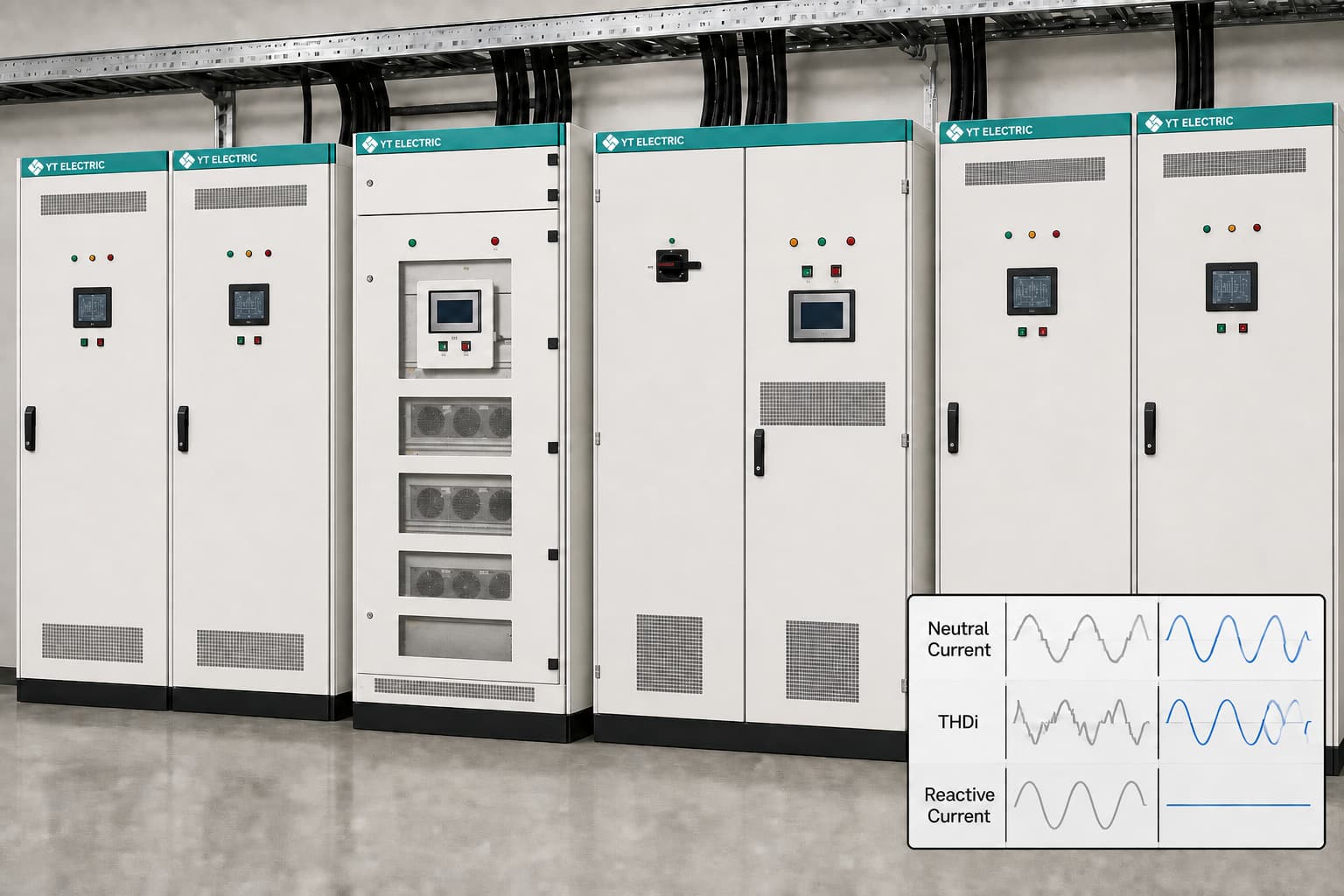
When induction motors, cranes, rolling equipment, or large VFD groups change load, the required reactive current changes with them. A fixed capacitor stage can be correct at one load point and excessive at another; excessive capacitive kvar may push the power factor leading and create switching stress.
An SVG uses a voltage-source inverter to inject leading or lagging reactive current. By controlling current instead of mechanically switching capacitor steps, it can track load changes rapidly and support voltage stabilization within the limits imposed by source impedance, transformer capacity, and its own kvar rating.
The value is not a universal power-factor number. The site team should log kW, kvar, power factor, voltage, demand interval, generator operating state, and capacitor-bank status over representative production cycles. That record distinguishes a true reactive-power problem from a harmonic measurement error or an upstream voltage issue.
Select capacity from measured RMS harmonic current and dynamic kvar, adding margin only for documented growth or redundancy. At 45°C ambient temperature full-load, the cabinet must still meet junction-temperature, airflow, and derating limits under actual dust, altitude, and ventilation conditions.
|
Site condition |
Measurement to collect |
Equipment direction |
Rating and installation logic |
|
480 V data center with UPS and IT loads |
THDi, neutral current, UPS loading, generator mode |
Four-wire AHF; SVG only if reactive demand warrants it |
Size AHF from simultaneous harmonic and neutral current; coordinate with UPS and generator protection |
|
VFD-dense textile or packaging line |
Harmonic spectrum, transformer temperature, feeder current |
AHF at MCC or PCC; SVG for varying kvar |
Select target harmonic orders and leave current headroom for production peaks |
|
Industrial site with power-factor penalties |
Interval kvar, demand profile, voltage variation |
SVG or hybrid SVG/capacitor arrangement |
Size for the observed dynamic kvar envelope; prevent leading power factor during low load |
|
High-temperature, dusty process area |
Ambient temperature, enclosure airflow, dust loading |
AHF/SVG with environmental design review |
Apply manufacturer derating and service-clearance requirements; do not assume nameplate output at elevated temperature |
|
Mining or generator-backed bus |
Source impedance, generator response, voltage dip events |
Coordinated AHF, SVG, or MV STATCOM study |
Determine whether LV compensation is sufficient or whether a STATCOM-level voltage-support study is required |
A 3-level AHF may suit applications where output-current quality, switching stress, and thermal margin matter, but topology is not a shortcut. Compare rated compensation current at declared ambient, overload policy, harmonic-order range, CT requirement, enclosure protection, and service access. For high power or medium-voltage fluctuation, consider a STATCOM study.
This is a representative scenario, not a named customer project or test report. A textile plant operates a 480 V MCC with VFD-driven spinning and air-handling motors; production ramps repeatedly switch the capacitor bank, while maintenance reports hot neutral terminations and intermittent trips.
The investigation logs PCC voltage and current, phase and neutral loading, THDi, capacitor status, transformer temperature, and VFD schedule. It points to changing nonlinear current and zero-sequence loading, not simply insufficient capacitor kvar.
The proposal places a four-wire AHF at the MCC bus, configured from measured harmonic orders and neutral current, and uses SVG only when logged kvar confirms dynamic demand. Review CT polarity, breaker coordination, short-circuit rating, capacitor-bank interaction, ventilation, and isolation.
After commissioning, compare results with pre-agreed PCC targets for THDi, neutral current, power factor, and voltage variation under the same production sequence. The site meter must record the actual result against applicable project and grid limits.
Start with logged harmonic current at the CT location, not the transformer nameplate or summed VFD ratings. Include simultaneous load, required harmonic orders, four-wire neutral current, documented load additions, and any reactive-current function.
Installation normally requires a planned isolation window for bus connection, CT installation, protection checks, and commissioning. A staged installation can reduce disruption, but the electrical work method, lockout procedure, and available feeder arrangement determine the actual outage requirement.
They require planned inspection rather than frequent component replacement. Check ventilation paths, fans, filters where fitted, cable terminations, CT circuits, controller alarms, capacitor-bank interaction, and recorded thermal conditions according to the product documentation and site maintenance procedure.
Yes, if the engineering review covers control coordination and protection. The review should verify capacitor resonance risk, UPS compatibility, generator voltage-regulator behavior, source impedance, CT locations, and the sequence used when the site changes between utility and generator supply.
An Active Harmonic Filter should be selected as a measured current-compensation system, not as a generic cabinet added after a trip event. SVG adds dynamic reactive power compensation where logged kvar demand and voltage behavior support the investment, while STATCOM becomes relevant when voltage stabilization is required at higher power or voltage levels.
YT Electric can review single-line diagrams, harmonic logs, ambient conditions, and PCC requirements before recommending AHF, SVG, or STATCOM capacity. Submit measurements for a site-specific assessment and commissioning checklist.
Explore YT Electric product specifications and application guidance: https://www.ytelect.com/blog/guide-to-selecting-active-harmonic-filters_b321
Reference: IEEE 519-2022, IEEE Standard for Harmonic Control in Electric Power Systems: https://standards.ieee.org/ieee/519/10677/
Need a site-specific solution? Share your single-line diagram, load list, measured power factor, THDi/TDD data, and ambient conditions with YT Electric. Our sales engineers can review the data and prepare a technical proposal



 IPv6 network supported