

 English
 français
 Deutsch
 español
 العربية
 中文

An Active Harmonic Filter (AHF) is a parallel-connected, closed-loop power-electronic device that measures load harmonic current with current transformers and injects an opposing current to cancel distortion at the point of common coupling (PCC). The engineering conclusion is blunt: an AHF is selected against the measured harmonic spectrum, load variability, site ambient temperature, and network impedance - not against the feeder's nameplate current alone.
A 480 V production bus can look stable until several VFD-driven lines ramp together: the neutral runs hot, the transformer temperature climbs, capacitor steps fail, and PCC THDi drifts past target. The symptom is a failed component; the cause is a filter chosen from one operating point.
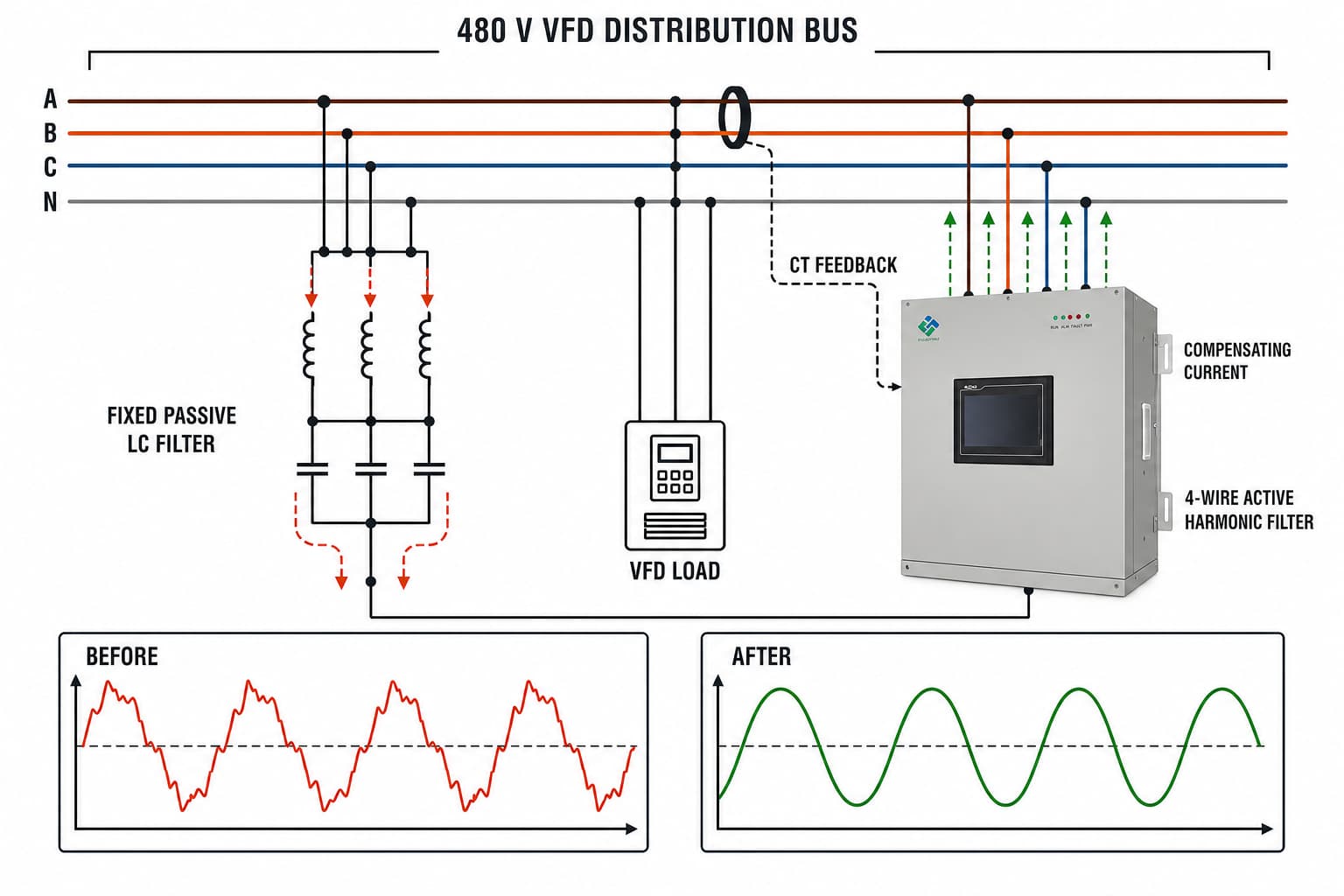
A detuned or tuned passive filter is a fixed LC branch: its impedance is lowest only at its tuned frequency. That assumption breaks when the plant adds VFDs, switches production states, runs on standby generation, or changes the load mix, because the dominant orders and their magnitudes move off the design point.
Upstream power-factor-correction capacitors matter too: capacitor and system inductance can form a parallel resonance that amplifies one order instead of attenuating it, so a filter that looked correct on paper can detune or magnify distortion after motors, transformers, or capacitor banks change. Passive designs therefore need an impedance study, and no filter can be selected from rated current alone.
THDi (total harmonic distortion of current) expresses the RMS value of every harmonic order above the fundamental as a percentage of fundamental current. A high THDi means extra RMS current flows through each cable, breaker, and winding, and a low total can still mask one dominant order sitting near a resonant frequency.
The consequence is thermal. I²R (copper) losses scale with the square of RMS current, so harmonics raise loss and temperature, and harmonic flux adds eddy and stray losses in transformer cores. Voltage distortion at the PCC then spreads to every load on the bus. Zero-sequence (triplen) harmonics - 3rd, 9th, 15th - add in the neutral instead of cancelling, so a neutral can overheat even when phase currents are balanced.
Measurement is the first engineering step, so a structured AHF selection guide begins with logged data, not a catalogue. Record THDi and TDD, individual orders and phase angles, voltage THD, phase and neutral RMS current, power factor, and reactive-power demand. CT placement then decides what the filter sees: the current transformers must measure the harmonic current the AHF will cancel, and mounting them on the wrong side of the PCC or of a capacitor branch makes the unit compensate the wrong current.
The AHF closes a measurement loop many times per mains cycle. Current transformers sample load current, the controller separates the fundamental from the unwanted harmonic components, and the inverter injects a matching current in the opposing phase through SPWM modulation. Because the reference is recalculated continuously, the unit tracks changing VFD, rectifier, UPS, and welding loads instead of staying tuned to one condition.
Topology and thermal design decide whether that control stays reliable. A 3-level topology splits the voltage transition into smaller steps than a 2-level inverter, reducing dv/dt and switching stress on the IGBTs; IGBT switching frequency, reactor losses, and airflow then set the real thermal margin. At 45 °C ambient the same nameplate current is harder to sustain, so specify verified full-load duty at the site temperature, altitude, and ventilation.
| Engineering factor | Passive harmonic filter | Active harmonic filter (AHF) |
|---|---|---|
| Operating principle | Fixed tuned LC branches, low impedance at designed frequencies | Closed-loop inverter injects measured harmonic current in opposing phase |
| Harmonic orders addressed | Effective mainly at the tuned orders | Multiple selected orders within the control range |
| Response to load change | Compensation shifts when the spectrum moves off the design point | Tracks changing load current within rated response and capacity |
| Resonance behaviour | Needs an impedance study; capacitor-network interaction can detune or amplify | Adds no tuned capacitor branch, but still needs a resonance assessment |
| Neutral and zero-sequence current | 3-phase designs do not cancel triplen neutral current | A 4-wire unit can compensate zero-sequence and neutral current |
| Reactive power | Fixed capacitor vars can become excessive at light load | Configurable dynamic reactive-power compensation where enabled |
| Footprint and maintenance | Large reactors and capacitors; inspect parts and detuning | Cabinet system; inspect cooling, fans, terminals, DC-link health |
| Best-fit condition | Stable spectrum with known dominant orders | Variable, multi-order, VFD/UPS/rectifier-heavy networks |
A line reactor or DC-link choke reduces the harmonic current a single drive draws at source. A detuned passive filter diverts specific orders and supplies fixed reactive power. An AHF cancels multiple orders dynamically and can also supply controlled reactive power and neutral-current compensation. A Static Var Generator (SVG) targets reactive power and voltage support rather than harmonic current, and hybrid schemes combine a smaller AHF with detuned capacitors or an SVG to split the duties.
| Site condition and measurement focus | Recommended engineering path | Capacity and installation logic | Acceptance evidence |
|---|---|---|---|
| Stable 6-pulse drives; dominant 5th/7th | Detuned passive filter after impedance and resonance study | Size from measured spectrum and fundamental vars; verify capacitor duty | Pre/post spectrum, capacitor current, PCC voltage distortion |
| Variable VFD lines or process ramps | Active Harmonic Filter | Compensation amperes from simultaneous harmonic current, diversity, growth, thermal derating | THDi and individual orders across production states |
| 4-wire office, data centre, or UPS | 4-wire AHF | Confirm neutral current, triplen spectrum, CT location, conductor rating | Neutral RMS current and phase balance |
| Generator-backed bus | AHF plus generator-compatibility review | Check generator reactance, load steps, control settings, minimum-load operation | Generator voltage and frequency response to steps |
| Capacitor failures or low power factor | Separate harmonic and var assessment; AHF plus SVG or detuned capacitors | Do not treat harmonic amperes as a kvar substitute; coordinate control modes | PCC THDi, power factor, capacitor current, resonance review |
| High ambient (~45 °C) or poor ventilation | AHF with verified thermal derating | Confirm full-load duty at site temperature, altitude, and airflow | Temperature-rise and current records at full load |
Size the AHF from the simultaneous harmonic current at the worst-case state, with margin for ambient derating, load growth, and required functions, then set the PCC target against utility requirements or the project's IEEE 519 assessment.
An AHF cannot remove weak-source voltage distortion beyond its current and voltage headroom, or fix a resonance it was not sized to handle, and its bandwidth and high-ambient derating set hard limits. Harmonic amperes are also not a substitute for required kvar: if the problem is power factor or voltage support, an SVG for reactive power and harmonic support may be the correct choice, and a dedicated Active Power Filter is the efficient answer only when harmonic current is the real constraint.
Size from the measured harmonic current at the simultaneous worst-case state, then add ambient-temperature derating, a load-growth allowance, and the required functions. Total feeder current or transformer kVA alone is not a sizing basis.
At minimum, log THDi and TDD, individual harmonic orders and phase angles, voltage THD, phase and neutral RMS current, power factor, reactive-power demand, and source impedance, with CT positions documented.
The connection point normally needs an approved isolation window for busbar, breaker, CT, and communication work. The outage plan depends on switchboard access, arc-flash procedure, spare feeders, and local rules.
Routine inspection covers cooling paths, fans, terminals, air filters, alarms, and logged currents; passive filters also need capacitor, contactor, fuse, and detuning checks. Payback varies with tariff, load profile, and loss reduction, so calculate it from the site's own energy data, not a fixed figure.
Choose a passive filter when measurements show a stable, well-defined spectrum and an impedance study supports a tuned design. Choose an AHF when the plant needs multi-order mitigation, changing-load tracking, neutral-current compensation, or controllable reactive power without adding fixed tuned capacitor branches. The AHF is better for variable conditions because its closed-loop injection follows the measured problem.
YT Electric can review logged power-quality data, the one-line diagram, ambient conditions, and planned expansion to define an AHF, passive filter, SVG, or coordinated SVG and AHF power-quality solution. For a side-by-side function comparison, see the difference between an SVG and an active harmonic filter, then share your single-line diagram, load list, power factor, THDi/TDD data, and ambient conditions with YT Electric so our sales engineers can prepare a technical proposal.
Reference: IEEE 519-2022, IEEE Standard for Harmonic Control in Electric Power Systems (standards.ieee.org).



 IPv6 network supported