

 English
 français
 Deutsch
 español
 العربية
 中文
中文
SVG and AHF maintenance is the scheduled inspection, measurement and component-replacement programme that keeps a static var generator (SVG) and an active harmonic filter (AHF) inside their design limits — stable reactive power compensation, a corrected power factor, and harmonic current below the limits agreed at the point of common coupling (PCC).
Most plants do not lose power quality equipment in one dramatic event. The first symptoms are secondary: a transformer that runs hot below its nameplate load, a capacitor bank that trips more often, a neutral that overheats, or a power-factor penalty that returns even though the SVG is still switching. For electrical engineers, EPC contractors, procurement teams and power quality consultants, a structured routine is the lowest-cost way to protect capital and avoid unplanned downtime.
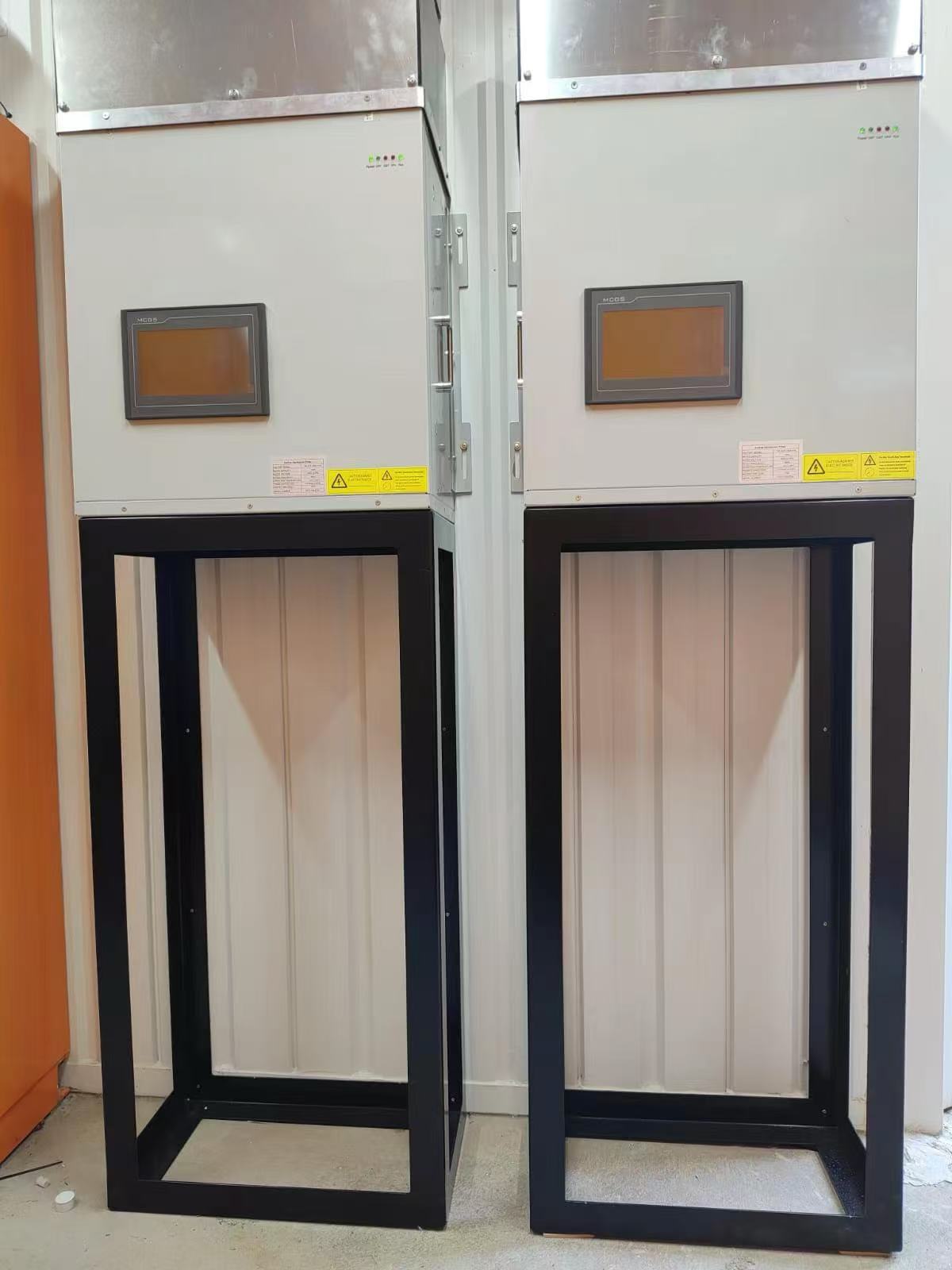
Figure 1: YT Electric SVG and AHF equipment — scheduled maintenance protects reactive power compensation and harmonic filtering performance.
These devices are exposed to the same electrical and thermal stress they are installed to correct, so their condition controls whether the installation stays compliant. A maintained system protects four things at once:
An SVG is a voltage-source converter connected in parallel with the bus. It measures load current and bus voltage continuously and synthesises a compensating current so that only the active component remains, holding the power factor close to unity and supporting voltage dynamically. YT Electric builds its SVG modules on a three-level topology, which lowers switching loss and output distortion and uses a switching frequency high enough to keep the injected current clean. See the full Static Var Generator range for the topology and ratings behind this design.
An AHF uses the same building blocks — an IGBT bridge, DC-bus capacitors, current sensors and a digital controller — but its control target is different. Instead of a single reactive component it measures the harmonic spectrum and injects an equal, opposite current for each harmonic order. Because correction is order-by-order rather than tuned to one frequency, an AHF does not introduce the resonance that fixed capacitor banks can create with the supply inductance. Product details are in the Active Harmonic Filter series.
The two topologies wear differently, so the first maintenance task is to know which symptom belongs to which topology. The comparison below drives both diagnosis and selection.
| Aspect | Static Var Generator (SVG) | Active Harmonic Filter (AHF) |
|---|---|---|
| Primary function | Reactive power compensation, power-factor correction, voltage support | Harmonic current mitigation, load balancing, displacement-factor correction |
| Control target | Fundamental reactive current | Individual harmonic orders |
| Converter topology | Three-level IGBT voltage-source converter | Three-level IGBT converter with harmonic detection |
| Response | Sub-cycle, continuous | Sub-cycle, order-by-order |
| Key measurements | Reactive power, power factor, bus voltage | THDi, individual harmonic orders, zero-sequence current |
| Main wear items | DC-bus capacitors, cooling fans, IGBT modules | DC-bus capacitors, cooling fans, current sensors |
| Risk if neglected | Utility penalty, resonance with capacitor banks | Transformer and neutral overheating, tripping of sensitive loads |
Cause: ripple current and thermal cycling dry out film and electrolytic capacitors. Consequence: DC-bus capacitance falls, ripple rises and the converter delivers less compensating current, so power factor or THDi drifts back with no alarm. Measurement: capacitance and equivalent series resistance (ESR) tested against end-of-life values, plus DC-bus ripple. Solution: replace the bank before output falls below the design requirement.
Cause: high dv/dt and repeated thermal cycling fatigue the power modules and their gate drives. Consequence: sporadic gate-drive faults, then module failure. Measurement: annual thermography, a review of switching behaviour and gate-drive alarms. Solution: correct cooling first, verify control parameters, and replace only the affected module.
Cause: dust on filters, heat sinks and fans blocks airflow. Consequence: cabinet temperature rises, components derate and capacitor life shortens. Measurement: log cabinet temperature and airflow, and check the filter differential. Solution: clean filters monthly and confirm the unit is still rated for continuous full-load operation at 45°C ambient.
Cause: a current transformer installed on the wrong side of the compensation point, or on the wrong phase, feeds the controller a false reference. Consequence: the unit compensates the wrong quantity and under-compensates, and on four-wire systems the zero-sequence current on the neutral stays high. Measurement: clamp-meter check of CT ratio and phase angle at the PCC. Solution: re-clamp the CT to the correct point and recalibrate the controller.
Once a fault is confirmed, adding capacity is not always the answer. The matrix links a measured symptom to the engineering decision and to the point at which a component should be renewed.
| Symptom / measurement | Likely cause | Recommended action | Renew or upgrade when |
|---|---|---|---|
| Power factor below target with the SVG at maximum output | Reactive demand has grown beyond design | Re-model the load and add module capacity | Available headroom falls below about 10% |
| THDi above the PCC limit with the AHF at maximum output | New non-linear load has been added | Re-measure the spectrum and add a module | Residual distortion still exceeds the limit after expansion |
| Rising DC-bus ripple, low capacitance | Capacitor aging | Schedule a capacitor replacement | Capacitance reaches the end-of-life value |
| Repeated overtemperature alarms in summer | Cooling or derating issue | Clean the cooling path and verify the 45°C rating | Overtemperature persists at rated ambient |
| Neutral overheating, high zero-sequence current | Triplen harmonics and load imbalance | Check CT placement, apply filtering and balancing | Current remains high after balancing |
| Capacitor bank resonance with the supply | Fixed bank interacting with harmonics | Reconfigure as a hybrid SVG plus capacitor, or detune the bank | The bank cannot be retuned safely |
Routine visual checks, filter cleaning and log keeping can be handled by plant maintenance staff. Call in a specialist for IGBT or PCB replacement, DC-bus capacitor replacement, controller recalibration after a grid fault, and SCADA communication troubleshooting. Misconfigured control parameters after a repair are a common cause of repeat faults. For a worked example of harmonic-driven overheating, see transformer overheating below rated load.
Clean air filters monthly and replace them when damaged. Test DC-bus capacitance and ESR annually and replace the bank when it reaches the end-of-life value.
On the load side of the compensation point, so the controller measures the current the equipment must correct, using the PCC as the reference. Verify ratio and phase after any modification.
When measured THDi at the PCC rises above the limit agreed with the utility while the AHF is already at maximum output — re-measure the spectrum and add a module.
Yes. Clean cooling and healthy capacitors keep the unit at rated output, which avoids power-factor penalties, protects transformers and neutrals, and defers replacement of the whole cabinet — the same lesson behind APFC panel troubleshooting.
Ready to set up a maintenance programme for your SVG and AHF equipment? Talk to a YT Electric engineer about inspection intervals, spare modules and replacement planning — contact amber@yt-electric.com.



 IPv6 network supported