

 English
 français
 Deutsch
 español
 العربية
 中文
中文
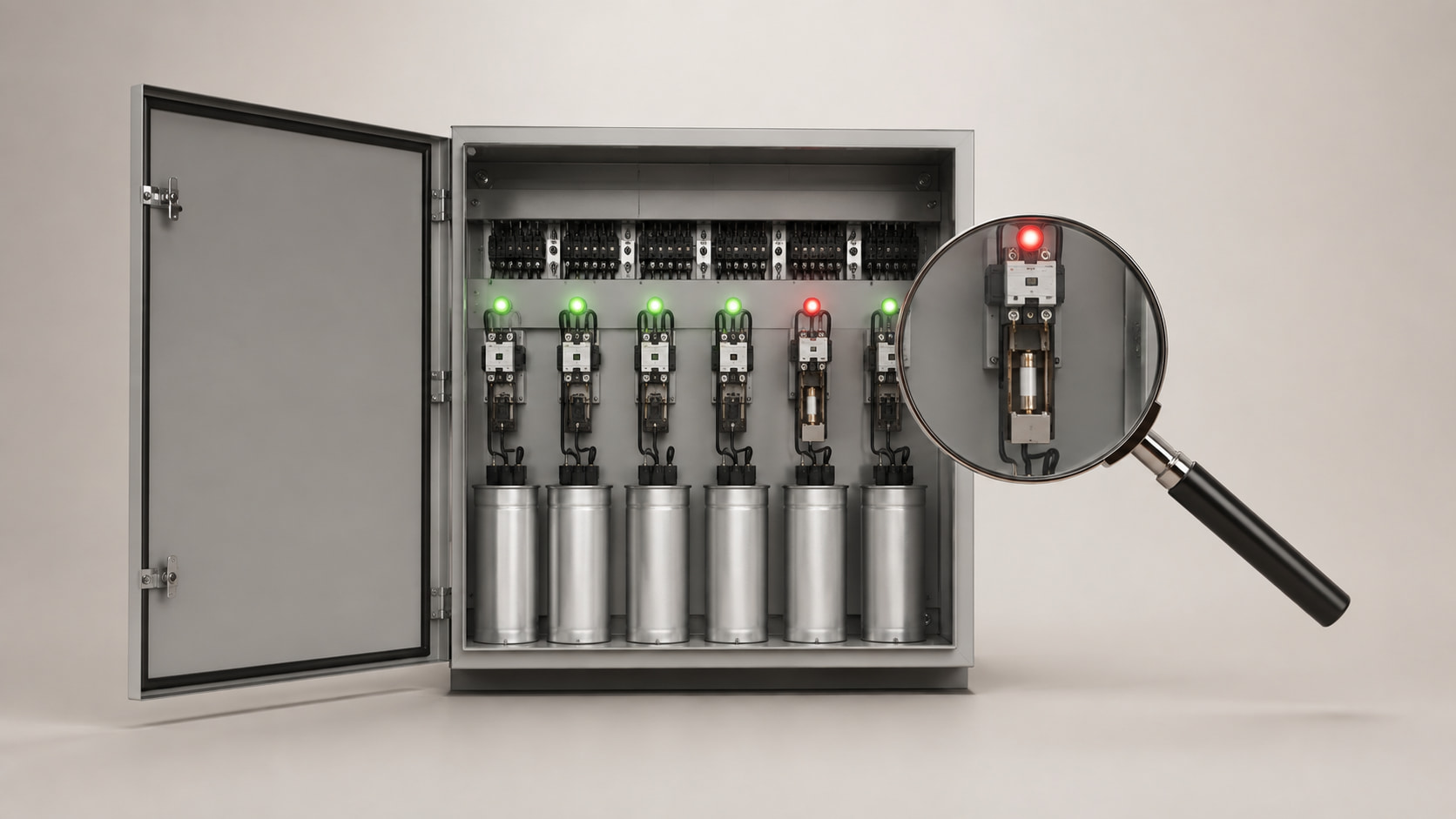
An automatic power factor correction panel may begin switching incorrectly, miss its target or repeatedly trip capacitor stages. A newly commissioned APFC panel can also fail from its first day.
The cause is not always a defective capacitor. CT installation, controller settings, harmonics, switching components and changing loads can all prevent correct operation.
Troubleshooting should follow measurements rather than trial-and-error replacement.
An APFC panel switches capacitor steps to supply reactive power required by inductive loads. It combines a controller, CT input, capacitors, switching devices, protection and, where required, detuning reactors.
The controller measures voltage and current, calculates reactive demand and selects the required stages. A fault in this chain produces incorrect compensation.
| Fault | Typical indication | First check |
|---|---|---|
| Incorrect CT installation | Controller shows the wrong power factor or direction | CT position, phase and polarity |
| Failed capacitor stage | Stage is commanded on but power factor barely changes | Stage current and fuse condition |
| Incorrect controller settings | Hunting, delayed response or leading power factor | Target, C/k value and switching delay |
| Harmonic distortion | Capacitor overheating, noise or repeated fuse failure | THDi, THDv and capacitor current |
| Load changes too quickly | Target is reached only briefly | Load trend and response time |
| Incorrect step sizing | Frequent switching between two stages | Step ratio and minimum step size |
| Excessive panel temperature | Thermal alarms or reduced capacitor life | Ventilation, fans and connections |
The current transformer is the controller’s sensing element. The wrong conductor, polarity or phase reference can reverse or corrupt its reactive-power measurement.
The CT should normally measure both load and capacitor current. On one feeder, it may not detect switching results. Parallel incomers may require dedicated logic.
Check CT ratio, direction, polarity, assigned phase and voltage reference against the controller diagram.
The controller may show a connected stage even when a fuse, contactor, capacitor or conductor has failed.
Measure every stage and compare its current with the expected value at actual voltage:
I = Q ÷ (√3 × V)
Phase currents should be balanced. Missing or low current indicates a fault requiring repair.
Incorrect settings can make a healthy panel behave like a faulty one. Check target power factor, CT ratio, smallest step, C/k value and switching delays.
The wrong response value can block switching or connect too many stages. Short delays increase wear; long delays leave loads under-compensated.
A target unnecessarily close to unity may produce leading power factor when load falls.
Capacitor impedance falls as frequency rises, attracting harmonic current generated by nonlinear loads. The result may be overcurrent, overheating, swelling or fuse failure.
Capacitors can also resonate with network inductance and amplify distortion near a dominant harmonic order.
Measure current and harmonics before replacing repeated fuse failures. Systems with many nonlinear loads may require detuned reactors or an Active Harmonic Filter.
Contactor-switched banks suit gradual load changes but may be too slow for welders, cranes, elevators and rolling mills.
Reactive demand may change again before the controller completes its delay and switches a fixed step. Frequent operation also shortens component life.
Solutions include thyristor switching, an SVG or hybrid compensation.
If the minimum capacitor step is too large, connecting it can move the system from lagging to leading power factor. Disconnecting it returns the system to lagging.
This hunting creates unnecessary switching and prevents stable correction.
Review the load profile, minimum step and sequence. Ageing capacitors may also deliver less than nameplate kVAr.
Capacitors, reactors, contactors and busbars produce heat. Blocked ventilation, failed fans, dust or high room temperature can exceed component limits.
Loose connections create resistance and hot spots that damage terminals and insulation without tripping the incomer.
Use thermal imaging under load. Check fans, filters, terminals and discolouration. Isolate and discharge capacitors before internal work.
| Symptom | Likely cause | What to measure or inspect |
| Power factor does not improve | Failed step, CT error or insufficient kVAr | Stage current, CT wiring and reactive demand |
| Power factor becomes leading | Excessive capacitance or controller setting | kVAr, target PF and step size |
| Stages switch repeatedly | Smallest step too large or unstable load | Switching log and load trend |
| Capacitor fuses keep blowing | Harmonic current, resonance or failed capacitor | Spectrum, capacitor current and capacitance |
| Capacitors swell or leak | Overtemperature, overvoltage or ageing | Voltage, temperature and physical condition |
| Contactor chatters or burns | Low control voltage or excessive switching | Coil voltage and switching frequency |
| Controller shows an unrealistic value | CT ratio, polarity or phase-reference error | Wiring and controller configuration |
Measure at the panel incomer and compare the results with the controller display. Record:
Voltage and phase current
kW, kVAr, kVA and power factor
True and displacement power factor
Current and voltage THD
Individual harmonic orders
Current of every capacitor stage
Panel temperature and switching sequence
Determine whether the fault is continuous or load-dependent. Test stages individually where permitted. Verify isolation and discharge before handling capacitor circuits.
| Confirmed problem | Suitable corrective action |
| Incorrect CT signal | Correct its position, ratio, polarity and phase reference |
| Failed capacitor stage | Replace the defective fuse, contactor or capacitor after finding the cause |
| Poor controller response | Reconfigure the target, C/k value, delays and step sequence |
| Harmonic overload | Apply detuning, harmonic filtering or redesigned compensation |
| Rapid reactive-power variation | Use thyristor switching, SVG or hybrid compensation |
| Stage hunting | Reduce the smallest step or revise the stage ratio |
| Excessive temperature | Restore ventilation and repair loose or overloaded connections |
The panel may be undersized, its CT incorrect or its stages failed. Harmonics can also reduce true power factor.
Repeated failure may indicate overcurrent, resonance, excessive voltage, a damaged capacitor or incorrect fuse rating. Find the cause before replacement.
Continuous switching suggests rapidly changing load, an oversized minimum step, incorrect response settings or a faulty CT signal.
Yes, but harmonics must be evaluated. Capacitors may require detuned reactors, and they must not be connected directly to a VFD output.
Frequency depends on load, temperature, dust and switching duty. Check current, protection, ventilation, connections and overheating.
APFC troubleshooting must examine the complete system. CT errors, failed stages, harmonics, unsuitable steps and heat can produce similar symptoms.
Measurements, switching records and thermal inspection reveal whether to repair a stage, change settings, revise the sequence or apply detuned or dynamic compensation.
A structured process restores reliable correction while reducing repeated failures and unnecessary replacement.



 IPv6 network supported