

 English
 français
 Deutsch
 español
 العربية
 中文

How to Size an SVG for an Existing Capacitor Bank: A Practical Hybrid PFC Guide
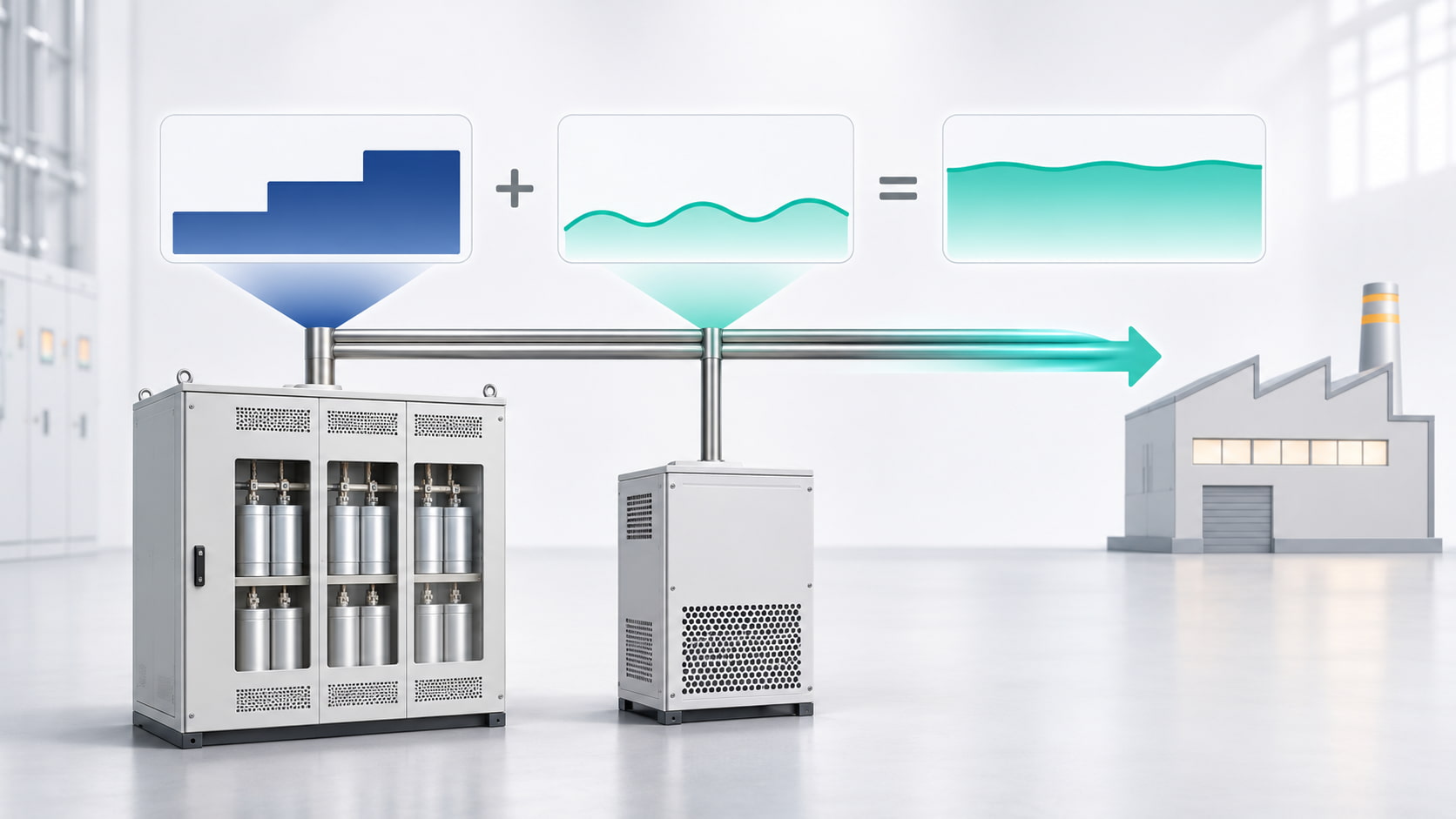
An existing capacitor bank provides economical bulk reactive power but may struggle with rapidly changing loads, uneven phases, or coarse steps. Adding a Static Var Generator (SVG) can close this gap without replacing useful equipment.
The SVG should not automatically match the facility’s entire reactive demand. In a hybrid system, the bank supplies the stable base requirement while the SVG handles residual, fast-changing, leading, or phase-specific demand. Sizing therefore depends on measured residual kVAr—not transformer size or bank nameplate rating.
A capacitor bank supplies reactive power in fixed steps. A 200 kVAr APFC panel, for example, may switch combinations of 25 or 50 kVAr stages. This works well with stable demand.
A bank cannot provide values between its step combinations. Switching and discharge delays also limit its response. A changing process may leave power factor below target, push it leading, or cause repeated switching.
An SVG injects or absorbs reactive current continuously. The bank covers the base load while the SVG trims the remaining error, reducing the required active capacity while retaining the cost advantage of capacitors.
Start with the objective: avoiding reactive-energy charges, releasing transformer capacity, reducing feeder current, or stabilizing power factor during production.
Do not assume 1.00 is always correct. Select a target that meets tariff and equipment requirements without causing unnecessary leading power factor.
For a steady operating point, the theoretical compensation requirement can be estimated with:
Qc = P × [tan(cos⁻¹ PF1) − tan(cos⁻¹ PF2)]
Where:
Qc is the required compensation in kVAr
P is active power in kW
PF1 is the measured power factor before correction
PF2 is the required power factor
The formula is a starting point; one operating point cannot size a dynamic system.
Record three-phase kW, kVAr, power factor, voltage, current, and capacitor-step status through a representative cycle, including peaks, light load, motor starts, and rapidly cycling equipment.
Log fast enough to capture changes the APFC controller misses. Bills or one handheld reading rarely reveal the peak residual kVAr.
Record whether residual kVAr is lagging or leading because the SVG may need to generate and absorb reactive power.
Do not subtract the bank’s nameplate rating without testing it. Confirm healthy steps, selected combinations, and the condition of contactors, fuses, capacitors, and reactors.
Capacitor output changes with voltage and frequency. A unit rated above the actual bus voltage delivers less than its nameplate kVAr. Use measured bank current and operating data where possible.
Decide whether to repair unavailable steps before sizing. Using an oversized SVG to conceal bank faults adds cost without resolving them.
The most useful sizing value is the reactive power remaining at the point of common coupling after the capacitor bank has operated.
Residual kVAr = load reactive demand − actual capacitor-bank output
Plot this value over time. Identify the highest lagging residual, largest leading excursion, duration, and rate of change. The SVG must cover this bidirectional range at the operating voltage.
If residual demand ranges from +80 kVAr lagging to −25 kVAr leading, the selection must cover 80 kVAr of capacitive correction and absorb 25 kVAr. Also consider measurement uncertainty, planned growth, ambient conditions, and manufacturer derating.
This is more reliable than matching the SVG rating to the bank.
| Site data or condition | Why it matters | Effect on SVG selection |
|---|---|---|
| Maximum residual lagging kVAr | Shows the largest remaining inductive demand | Establishes the minimum capacitive compensation range |
| Maximum residual leading kVAr | Reveals overcompensation at light load | Confirms the required inductive absorption capability |
| Smallest capacitor step | Defines the bank’s control resolution | SVG may need to trim the gap around each step |
| Rate of load change | Shows whether the bank can follow the process | Fast changes strengthen the case for dynamic capacity |
| Phase-current unbalance | Indicates unequal phase requirements | May require a four-wire SVG sized by phase |
| Bus voltage and ambient temperature | Affect equipment output and thermal capacity | Apply the manufacturer’s operating and derating data |
| Harmonic measurements | Separate reactive-power and distortion problems | May require an AHF or a coordinated multifunction solution |
A three-wire SVG suits balanced three-phase correction. Significant single-phase loads and unequal currents may require a four-wire SVG with independent phase compensation.
For four-wire selection, review residual demand and equipment limits per phase, not only total kVAr. An SVG is not automatically a neutral harmonic filter.
Capacitor banks interact with system inductance and may increase resonance risk. Review voltage and current harmonics, reactor tuning, and nonlinear loads before retaining the bank.
An SVG primarily corrects reactive power. Do not treat it as an Active Harmonic Filter unless rated for both functions. Harmonic problems may require an AHF, detuned bank, or coordinated solution.
The SVG must measure the residual created by the load and bank, so CT location, polarity, phase sequence, and controller boundaries matter.
The bank should handle slower bulk compensation while the SVG corrects the remaining error. Conflicting setpoints can cause step hunting, leading power factor, or opposing operation.
Commission under heavy load, light load, and switching events. Verify power factor, residual kVAr, bank steps, SVG loading, and phase currents.
No. Size it from the maximum residual after the healthy bank operates. Its rating may be considerably smaller than the bank capacity.
Yes, within its bidirectional rating. Persistent overcompensation still requires review of capacitor steps, controller settings, CT placement, and light-load operation.
Not without assessment. Check harmonic current, resonance, reactor tuning, voltage, and thermal loading. An SVG does not make an unsuitable bank safe.
There is no universal percentage. Consider measurement uncertainty, planned loads, duty cycle, temperature, voltage, and manufacturer derating. Oversizing does not solve coordination problems.
SVG sizing beside an existing bank is a residual-demand exercise. Measure the load cycle, confirm actual bank output, identify lagging and leading residual kVAr, and check unbalance, voltage, temperature, and harmonics.
The bank can supply economical base compensation while the SVG provides fast, continuous correction. CT placement and coordinated controls are as important as kVAr rating.
YT Electric can review your power-quality records, capacitor-bank configuration, residual kVAr profile, harmonic spectrum, and future load plans to help size and configure an SVG for a reliable hybrid power factor correction system.



 IPv6 network supported