

 English
 français
 Deutsch
 español
 العربية
 中文

Can an SVG and Capacitor Bank Work Together? CT Placement, Control Logic, and Common Mistakes
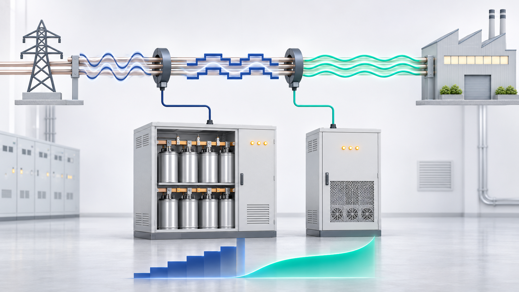
Yes. A well-designed hybrid arrangement combines economical capacitor-based bulk compensation with the speed and precision of a Static Var Generator (SVG).
Connecting both devices to one busbar is not enough. Each controller needs the correct current signal and a defined priority. Incorrect CT placement or conflicting setpoints can idle the bank, overload the SVG, create leading power factor, or cause repeated switching.
A capacitor bank supplies reactive power in fixed stages and suits stable base demand. Contactor and discharge requirements limit its speed, while its smallest step determines control resolution.
An SVG injects or absorbs reactive current continuously, follows fast changes, and corrects the residual between steps. A suitable four-wire SVG can also compensate unequal phase demand.
Together they can provide:
Economical bulk kVAr from the capacitor bank
Rapid adjustment and residual correction from the SVG
Limited leading-reactive-power absorption by the SVG
Continued use of a healthy, suitable existing bank
Performance depends on their measurement and control zones.
Both systems calculate reactive demand from current-transformer signals. CT position defines which loads and compensation currents each controller can see.
For an automatic bank, the CT is normally upstream of the controlled loads and bank. It must see source-current changes when steps switch; otherwise the controller may keep requesting compensation.
An SVG may use grid-side or load-side measurement. Its CT position relative to the bank determines whether it sees uncompensated demand or the residual after bank operation.
There is no universal diagram. Follow both manufacturers’ single-line diagrams and confirm priority before wiring.
CT direction, polarity, phase sequence, voltage reference, and programmed ratio must agree with the controller.
A reversed CT can make inductive current appear capacitive. Incorrect phase mapping can produce the wrong angle and worsen compensation.
Three-CT measurement is preferable where phase unbalance matters. A one-CT arrangement may not represent unbalanced loads.
CT secondary circuits require qualified handling, suitable burden, and must never be left open while energized.
Do not assume an existing metering CT can simply be shared. Its ratio, accuracy class, burden, secondary rating, and isolation arrangement must suit every connected device. A dedicated CT or an approved transducer output can make measurement boundaries clearer and troubleshooting safer.
Control hierarchy must be chosen deliberately, not left to independent controllers with identical targets.
Here, the bank provides slower base compensation and the SVG handles residual error, reducing active-device capacity and loading.
The bank must recognize sustained demand without being masked by the faster SVG. Coordinated delays, different control bands, reserve settings, or a master controller may be required.
Alternatively, the SVG responds first and the bank covers demand beyond its range. This prioritizes speed but may leave the bank lightly used.
Manufacturer diagrams may specify CT positions for this sequence. The architecture must match sizing and operating objectives.
For larger systems, a hybrid controller or PLC can assign base and dynamic requirements. This needs compatible communications, alarms, and failure logic.
The design should also define fallback operation. If the SVG trips, the bank must not switch beyond its safe operating limits. If a capacitor step fails, the SVG should not be expected to carry the missing kVAr indefinitely unless its rating and thermal duty allow it.
| What you observe | Likely integration problem | First check |
|---|---|---|
| Capacitor bank stops switching after SVG installation | Fast SVG correction hides demand from the APFC controller | CT boundaries, target settings, delays, and priority logic |
| Capacitor steps switch repeatedly | Overlapping setpoints or insufficient deadband | Controller targets, step size, response delay, and discharge time |
| Power factor becomes leading at light load | Bank remains connected too long or cannot see the SVG response | Bank CT position, step-off logic, and minimum-load operation |
| SVG reaches full output while healthy bank remains idle | Incorrect operating priority or failed bank control | Bank status, CT signal, controller mode, and SVG limit settings |
| Compensation makes power factor worse | CT polarity, voltage reference, or phase sequence is incorrect | Compare wiring with the approved single-line diagram |
| Controller readings disagree with the power-quality analyzer | Wrong CT ratio, different measurement boundary, or phase mapping | Ratios, locations, phase assignments, and instrument timestamps |
Two controllers chasing one target at different speeds may oppose each other. The SVG can hide demand before the bank reacts, or the bank may add an unnecessary step.
Use defined priorities, setpoints, deadbands, and delays based on step size and SVG operating range.
Blown fuses, weak capacitors, worn contactors, or unavailable steps change real output. Nameplate capacity alone is insufficient.
Test and repair the bank before hybrid commissioning.
An SVG primarily compensates reactive power and does not automatically remove current harmonics.
Measure THDi and THDv, check resonance and detuning, and use an Active Harmonic Filter when required.
A system stable during production may overcompensate at night. Test heavy load, light load, load removal, starts, and process transitions.
Record source power factor, residual kVAr, SVG loading, step state, and phase currents.
Before energizing, confirm the single-line diagram, ratings, protection, CT ratios, polarity, phase sequence, and earthing.
Where permitted, commission each device independently. Confirm every step changes reactive power correctly and the SVG can generate and absorb kVAr.
Then observe a complete coordinated cycle. Verify the bank’s share, SVG reserve, switching frequency, and leading-power-factor behavior.
Only when explicitly permitted. Check CT burden, secondary rating, measurement boundaries, and controller isolation. Dedicated signals are often easier to troubleshoot.
Either can work. Bank-first favors economical base correction; SVG-first favors immediate response. CT arrangement and control logic must match the sequence.
The SVG may correct demand before the APFC controller sees a sustained error. Review CT locations, limits, targets, deadbands, and priority.
Yes, with inductive absorption capacity and coordinated controls. Do not use it to hide oversized steps, wiring errors, or unsuitable settings.
An SVG and capacitor bank can work together, but they must be treated as one system. CT location determines what each controller sees; polarity, phase mapping, setpoints, delays, and priority determine the response.
Choose which device operates first, verify the bank, and commission across the load range. Proper coordination combines economical bulk kVAr with fast, precise correction.
YT Electric can review your single-line diagram, CT arrangement, capacitor-step configuration, load profile, and power-quality measurements to help design and commission a stable hybrid SVG and capacitor-bank system.



 IPv6 network supported