

 English
 français
 Deutsch
 español
 العربية
 中文

Capacitor bank overheating after adding VFDs is a power quality symptom, not a capacitor defect. VFD rectifiers inject harmonic current, the bank offers a low-impedance path at those frequencies, and parallel resonance between the bank and the supply can amplify that current until fuses open, contactors chatter and capacitor cans swell. A capacitor bank supplies reactive power to correct power factor; it does not remove harmonics, so a kvar rating that suited linear loads can become unreliable once the load mix changes.
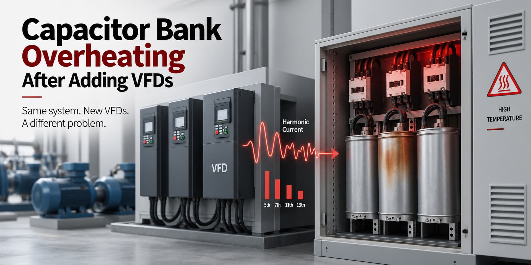
The compensation cabinet ran for years without problems. Then a new drive line or a batch of VFD-driven pumps and fans was commissioned, and within weeks operators report fuses blowing without a clear fault, contactors humming or welding shut, and swollen capacitor cans. The equipment did not change;
the electrical environment did.
A variable frequency drive converts incoming AC to DC, then re-creates a controlled AC output. In a modern 3-level topology the output stage switches IGBTs at a switching frequency in the low-kilohertz range, producing fast voltage edges (high dv/dt) that the motor insulation and output filters must handle. The input rectifier is different: it draws current only when the DC link needs charging, so the line current is a series of pulses, not a clean sine wave.
For a six-pulse rectifier the characteristic harmonics are the 6k ± 1 orders, so the 5th, 7th, 11th and 13th dominate. At 50 Hz the 5th harmonic sits at 250 Hz and the 7th at 300 Hz. One small drive may be harmless, but a dozen drives on the same low-voltage bus can push distortion above the 5% design target at the point of common coupling.
A capacitor's impedance falls as frequency rises: at the 5th harmonic it is roughly one fifth of its 50 Hz value, at the 7th about one seventh, so harmonic current prefers the capacitor path over the rest of the network. The bank's capacitor RMS current is the vector sum of the fundamental and every harmonic current, and losses rise with the square of that current. That is why a bank correct in kvar can still overheat.
Every capacitor bank forms a parallel resonant circuit with the transformer and supply inductance; the resonant order can be screened with the ratio of short-circuit power to capacitor rating (hr ≈ √(Ssc / Qc)). If that order falls close to the injected 5th or 7th harmonic, the impedance at that frequency becomes very high and the bank circulates a large harmonic current instead of the supply.
The results are repeated fuse failure, welded contactors, swollen capacitors and nuisance breaker trips. Replacing units restores operation briefly, then fails again because the replacement parts never addressed the root cause.
Selection starts with data. A power quality analyser should log the harmonic spectrum over a full production cycle, and the measurement point matters: distortion must be evaluated at the PCC (point of common coupling) and at the capacitor bank, with current transformers (CTs) placed so that the load and bank currents are both visible. Record voltage and current distortion (THDu and THDi), the 5th and 7th harmonic currents, capacitor RMS current, bank kvar, reactor detuning, transformer rating and cabinet temperature under 45 °C full-load conditions. See how to read a power quality report.
| Observed condition | Key measurement | Indicated direction |
|---|---|---|
| Fuses blow, contactors chatter | Bank RMS and 5th/7th current | Review detuning, resonance |
| Cabinet hot, no electrical fault | Cabinet temperature, ventilation | Check mechanical, thermal |
| High THDi, acceptable power factor | Harmonic spectrum at PCC | Active harmonic filter |
| Low power factor, moderate THDi | kvar demand, resonant order | Detuned bank or SVG |
| High kvar demand and high THDi | kvar plus harmonic current | Hybrid system |
Options range from a detuned reactor bank to an active harmonic filter (AHF), a static var generator (SVG), or a hybrid system combining both.
| Technology | Purpose | Best for | Limitation |
|---|---|---|---|
| Plain capacitor bank | Reactive power only | Linear loads | Resonance risk |
| Detuned capacitor bank | Shifts resonance below 5th/7th | Moderate distortion | No harmonic removal |
| Passive harmonic filter | Absorbs tuned orders | Stable single-order loads | Sensitive to network change |
| Active harmonic filter (AHF) | Cancels harmonic current | Meeting THDi limits | Current rating, CT placement |
| Static var generator (SVG) | Stepless reactive power | Fast load changes | Not a harmonic filter |
| Hybrid system | Capacitor plus active part | High kvar and distortion | Needs coordinated design |
A detuned bank adds a series reactor to each capacitor step, shifting the resonant frequency below the lowest harmonic that must be avoided, so the 5th and 7th are no longer amplified. Common detuning factors of 5.67%, 7% and 12.5% move the tuning order to roughly 4.2, 3.8 and 2.8 (about 210 Hz, 189 Hz and 141 Hz at 50 Hz). The reactor must match the capacitor rating, or it becomes a heat source.
An active harmonic filter measures load current with external CTs, calculates the harmonic components in real time and injects an equal and opposite current to cancel them, reducing THDi at the CT location towards a target. It does not create resonance with the supply, but it must be rated for the harmonic current it will cancel, and its CTs must sit on the correct side of the point where harmonic and bank currents separate.
A static var generator injects or absorbs reactive current continuously, correcting power factor without steps and staying stable in a harmonic-rich network where a plain bank is not. It follows load changes fast and can support voltage, but its main job is reactive power, not harmonic cancellation.
A hybrid reactive power compensation system uses a controlled capacitor bank for the steady reactive base and an AHF or SVG for the fast or harmonic part, often the lowest overall cost when a large kvar demand and significant harmonic current exist together.
Match the device to the measurement. A single analyser reading is rarely enough, so log a full production cycle and capture the worst-case operating point. If a plant already has a capacitor bank and new VFDs are planned, review the compensation design before the drives are commissioned, not after the first fuse failure.
If the bank is needed mainly for fundamental reactive power, THDi is moderate and the measured resonant order is safely away from the 5th and 7th, replacing standard capacitors with a detuned bank and matched reactors is the simplest repair.
If harmonic current must be removed to meet a distortion limit, an AHF is the direct tool. If the main need is fast, continuous reactive power, an SVG is the better fit, with an AHF added when harmonic limits apply. For matching reactive capacity to the load, see SVG sizing for power factor correction.
Yes, if the bank is verified for the new harmonic environment. Standard capacitors in a harmonic-rich system should be reviewed, and most VFD-heavy plants either upgrade to a detuned bank or remove the harmonic current with an AHF.
Measure the harmonic spectrum and capacitor current. If the 5th or 7th harmonic current in the bank is disproportionately high, if fuses fail repeatedly without a fault, or if the resonant order sits close to a dominant harmonic, resonance is the likely cause.
Choose a detuned bank when the main need is reactive power and distortion is moderate. Choose an AHF when a harmonic limit must be met and distortion reduced. Many industrial projects use both.
Detuned banks need periodic checks of capacitors, reactors, contactors and ventilation; AHF and SVG units mainly need clean airflow and correct CT wiring. Payback depends on tariff, load profile and loss reduction, so calculate it from measured data.
YT Electric supplies AHF, SVG and hybrid reactive power compensation systems for industrial plants, data centres and EPC projects. Send your measurement data to our engineering team to confirm the right configuration.
Capacitor bank overheating after adding VFDs is a signal that the harmonic environment has changed, not proof that the capacitors were poor quality. Measure THDi, THDu, capacitor RMS current and the resonant order at the PCC, then choose between a detuned bank, an AHF, an SVG or a hybrid system. Treat overheating as a power quality problem, and the repair will last.



 IPv6 network supported