

 English
 français
 Deutsch
 español
 العربية
 中文

Ask a plant engineer what their harmonic problem looks like, and you will usually get the same three numbers: 5th, 7th, 11th. Those are the characteristic orders of a balanced three-phase load, the ones every filter is tuned for, and the ones most harmonic studies report first.
Then the filter goes in, the 5th and 7th drop as promised — and the transformer still runs hot. The neutral still carries current it should not. Something in the spectrum is still there.
In medium-frequency melting shops and rectifier plants, that "something" is usually the even orders: 2nd, 4th, 6th — and further up.
Even-order harmonics appear whenever three-phase symmetry breaks. In practice that means:
None of these are exotic. They are ordinary conditions in exactly the industries where harmonic problems are most expensive.
And they are easy to under-estimate, because the limits themselves are modest: IEEE 519 caps even-order harmonics at 25% of the corresponding odd-order limit. A 2nd harmonic at 1% looks negligible next to a 5th harmonic at 4%. But even-order content behaves differently — it drives DC flux in transformer and reactor cores, produces asymmetric heating, and can push a core toward saturation long before the total THD figure looks alarming.
Most active filters are engineered — correctly — around the odd-order spectrum. That shows up in three ways:
The result is a filter that does exactly what its specification says, on a site that needed something the specification never asked for.
Our units are built to compensate even and odd orders in the same device — 2nd, 4th, 6th alongside 3rd, 5th and 7th — across the bands that actually carry pollution in industrial grids.
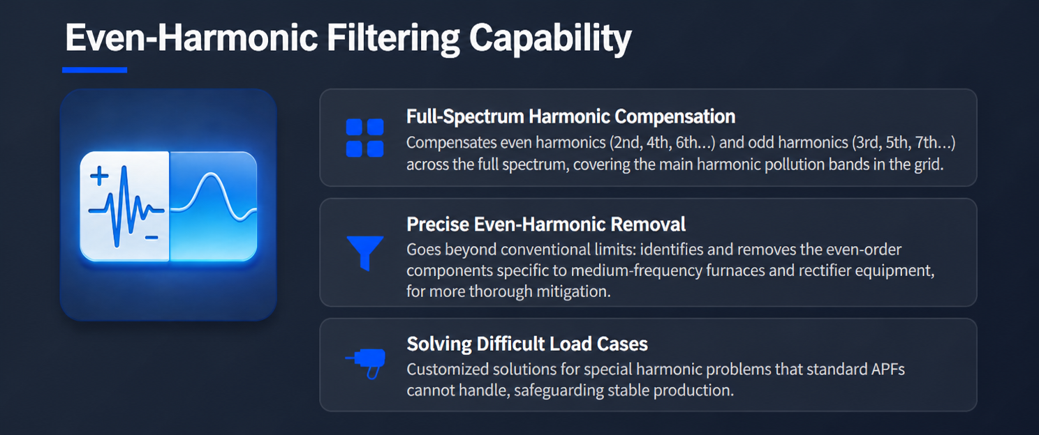
The second point in that figure is the one that matters commercially. Detecting and removing an even-order component demands a different detection strategy from the one used for characteristic harmonics — the unit has to separate a genuinely small, symmetry-breaking signal from the noise that surrounds it, then act on it without destabilising the control loop. That is engineering work, not a checkbox in a datasheet.
Any filter can be specified for a clean bus. The question is what happens when the bus is already badly distorted before the filter is connected.
On a recent field installation, phase voltage THD measured 30.7% / 27.4% / 28.6% — roughly double the level at which many standard units begin to current-limit, derate, or drop out of regulation. The unit kept compensating normally, holding a stable 151–156 A RMS per phase at 50 Hz.
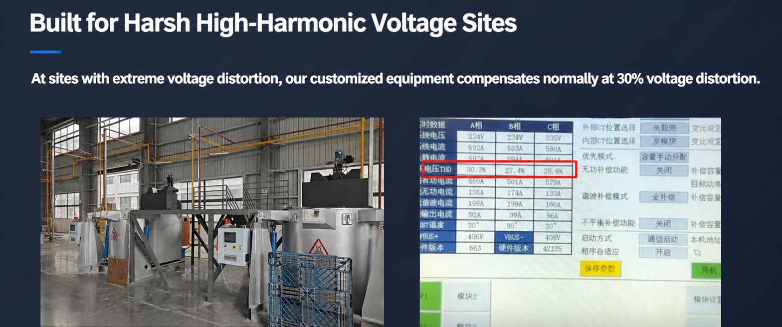
This is the difference between a product validated in a laboratory and one validated on a grid. At 30% voltage distortion, the grid voltage is no longer a clean reference — zero crossings drift, the PLL is under stress, and the current loop is being asked to track a reference derived from a badly deformed signal. Units that quietly stop working rarely announce it; they simply stop contributing, and the site blames the load.
Compensation current is only useful if it is clean. A filter that injects a ragged, spike-laden current trades one distortion problem for another — extra high-frequency content, additional reactor heating, audible noise, and a waveform that fails its own commissioning test.
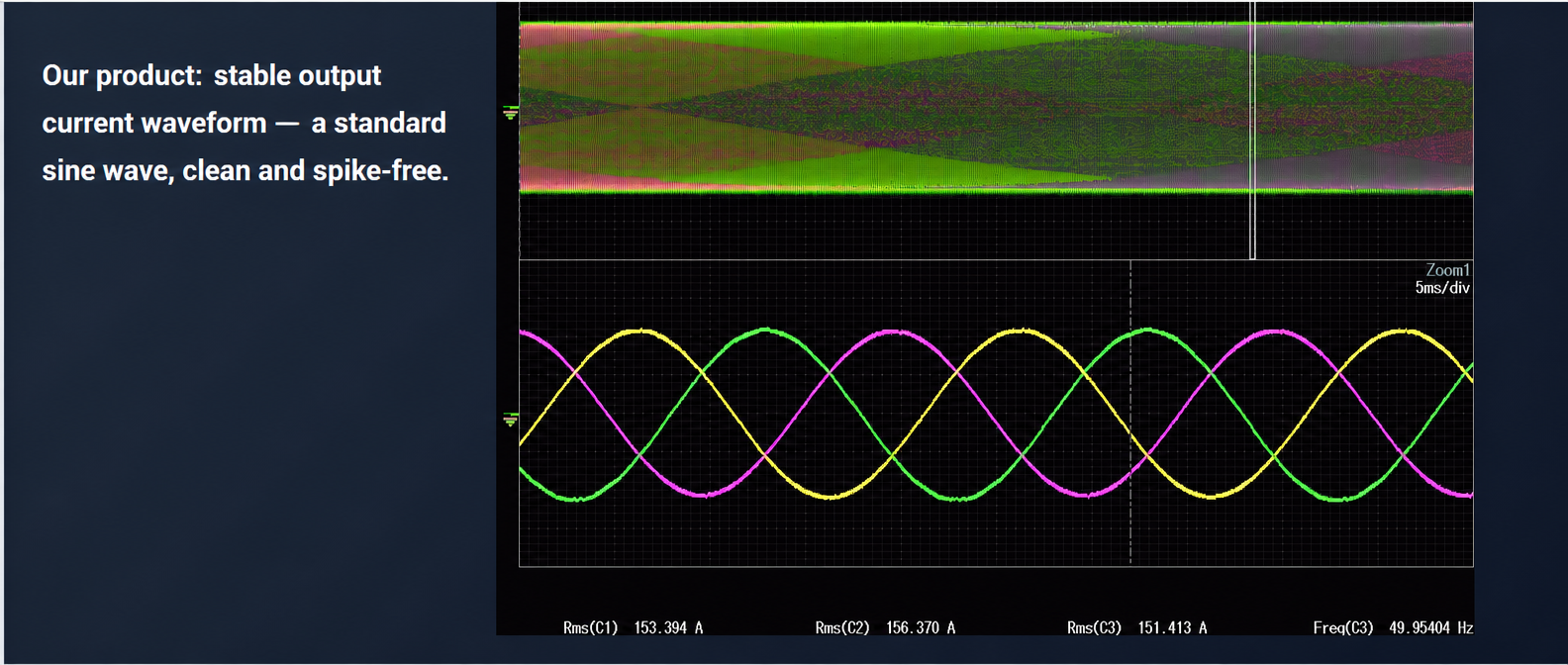
Spike-free output is not a cosmetic property. It is the evidence that the switching strategy, the output filter and the current loop are working together rather than fighting each other.
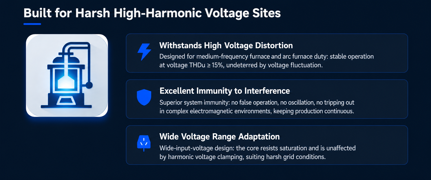
If you are buying an active filter for a furnace or rectifier site, five questions separate a real answer from a brochure:
A vendor who can answer all five has done the work. A vendor who answers three has a product that will work on somebody else's site.
If you are dealing with medium-frequency furnaces, rectifier banks, or any non-linear load where conventional filters cannot hold regulation, send us your harmonic spectrum and voltage THD data. We will tell you honestly whether our equipment is the right fit — and if it is not, what would be.



 IPv6 network supported