
 English
 français
 Deutsch
 español
 العربية
 中文
中文

SiC MOSFET Active Harmonic Filter for Industrial THDi Correction
A textile mill in Vietnam replaced its capacitor banks three times in 18 months. Each failure the same pattern: capacitor cans bulged, contactors welded shut, and fuses blew during the afternoon shift when 85% of the VFD-driven spinning frames ran simultaneously. The plant needed a SiC MOSFET active harmonic filter to solve the root cause, but the engineering team had only evaluated passive compensation options.
The root cause was not defective capacitors. The plant's 400 V bus carried a THDi of 32%, dominated by 5th and 7th harmonic currents from VFD front-end rectifiers. The passive capacitor bank formed a parallel resonance near the 7th harmonic, amplifying the distortion instead of correcting power factor.
The maintenance manager knew the problem. He lacked a solution that could operate at 40°C ambient, handle rapid load swings, and deliver measurable THDi reduction without creating new resonance paths.
Passive harmonic filters tune to a specific harmonic order. They inject fixed reactive power regardless of load condition. When a textile plant's VFD count varies from 30% to 100% of installed capacity within a single shift, passive banks oscillate between under-compensation and over-compensation — both conditions degrade power quality.
Active harmonic filters measure load current in real time. They inject equal and opposite harmonic currents to cancel distortion at the PCC. The compensation tracks the load harmonic spectrum every 40 microseconds.
But the semiconductor that generates this compensation current determines filter performance under thermal stress, high switching frequency, and distorted grid voltage.
A conventional active harmonic filter uses Si IGBT modules switching at 12–16 kHz. The IGBT's tail current during turn-off forces a design trade-off: increase switching frequency to improve harmonic cancellation waveform quality, or reduce it to limit switching losses. Engineers cannot optimize both simultaneously.
SiC MOSFET eliminates this trade-off. Its body diode exhibits zero reverse recovery charge. Turn-off occurs without tail current. The device switches at 30–50 kHz with lower total losses than an IGBT at 16 kHz.
Three measurable advantages translate directly to field performance:
1. Higher switching frequency produces a cleaner compensation current. The output LCL filter handles less ripple, so the inductor runs cooler and occupies less cabinet space.
2. Lower switching losses reduce heat rejection by approximately 30%. A 100 A SiC module dissipates roughly 850 W versus 1,200 W for an equivalent Si IGBT module. This difference proves critical in Southeast Asian electrical rooms where ambient reaches 40–45°C.
3. Controlled dv/dt — SiC gate drive circuits shape the switching edge below 5 kV/μs. This protects motor winding insulation in VFD-heavy plants where reflected wave phenomena already stress stator windings.
|
Parameter |
Si IGBT AHF (2-Level) |
SiC MOSFET AHF (3-Level) |
|
Switching frequency |
12–16 kHz |
30–50 kHz |
|
Compensation bandwidth |
Up to 25th harmonic |
Up to 50th harmonic |
|
Step response time |
< 300 μs |
< 100 μs |
|
Power loss per 100 A module |
~1.2 kW |
~0.85 kW |
|
Full-load ambient rating |
40°C (derating above) |
45°C (no derating) |
|
Output current THD |
< 5% |
< 3% |
|
dv/dt at load terminals |
3–6 kV/μs (uncontrolled) |
< 5 kV/μs (controlled) |
|
Module lifetime at rated conditions |
~80,000 hours |
~120,000 hours |
|
Audible noise at 1 m |
65–72 dB(A) |
55–62 dB(A) |
A 3-level NPC or T-type topology splits the DC bus with a neutral point clamp. Each switching device sees half the DC bus voltage. The output voltage switches between three levels instead of two, delivering three practical benefits for AHF applications:
First, the output voltage step halves. The LCL filter inductor experiences half the volt-second stress, so core losses decrease.
Second, the effective ripple frequency doubles relative to the device switching frequency. A 40 kHz switching rate produces an 80 kHz ripple component, requiring a much smaller filter inductor.
Third, neutral-point control handles zero-sequence harmonics — 3rd, 9th, 15th — directly. Two-level inverters cannot cancel zero-sequence currents without adding a fourth leg.
The most common specification error is selecting AHF capacity based on transformer kVA rating rather than measured harmonic current.
A 2,000 kVA transformer feeding mixed VFD and linear loads may produce only 400 A of total harmonic current. Specifying a 500 A AHF wastes budget and cabinet space. A 300 A unit with 15% headroom costs less, occupies the same electrical room with room to spare, and achieves identical THDi correction.
The correct selection method records the load current THDi and RMS spectrum at the point of common coupling over a full production cycle — not a snapshot measurement. Textile mills, automotive assembly lines, and food processing plants all show harmonic current variation of ±40% across a shift. A 30-minute measurement misses the worst-case condition.
|
Application |
Typical THDi (pre-correction) |
Dominant Harmonics |
Recommended AHF per 1,000 kVA Transformer |
Correction Target |
|
Textile mill (VFD spinning frames) |
28–35% |
5th, 7th, 11th |
250–350 A |
THDi < 5% |
|
Plastic injection molding plant |
20–28% |
5th, 7th |
200–300 A |
THDi < 5% |
|
Data center (UPS + cooling VFDs) |
15–22% |
5th, 7th, 3rd (neutral) |
150–200 A (3P4W) |
THDi < 5%, neutral < 50 A |
|
HVAC chiller plant |
25–35% |
5th, 7th, 11th, 13th |
250–350 A |
THDi < 5% |
|
Steel rolling mill |
30–40% |
5th, 7th, 11th, 13th |
350–500 A |
THDi < 8% |
|
Food processing (conveyor VFDs) |
18–25% |
5th, 7th |
150–250 A |
THDi < 5% |
All ratings assume 400 V, 50 Hz, 40°C ambient. For 45°C ambient operation, add 10% capacity margin.
An active harmonic filter connects in parallel with the load at the main distribution board. CTs clamp around the incoming busbars — no busbar disconnection required. The AHF power cables terminate at a spare circuit breaker. Commissioning takes 4–6 hours while the plant continues normal operation.
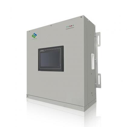
Wall-mount modules to 150 A mount beside the switchboard. Floor-standing cabinets from 200 A to 600 A occupy approximately 1 m² per unit. Multiple units operate in parallel with automatic current sharing.
[ ]
]
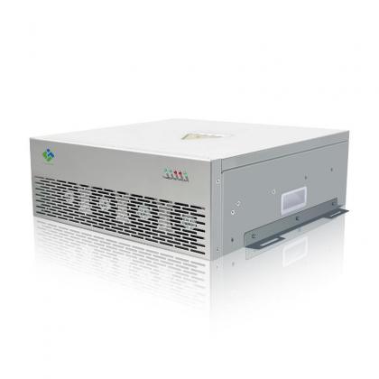
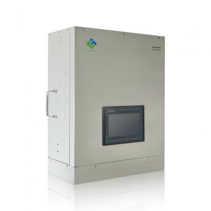
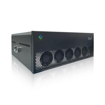
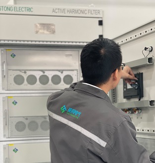
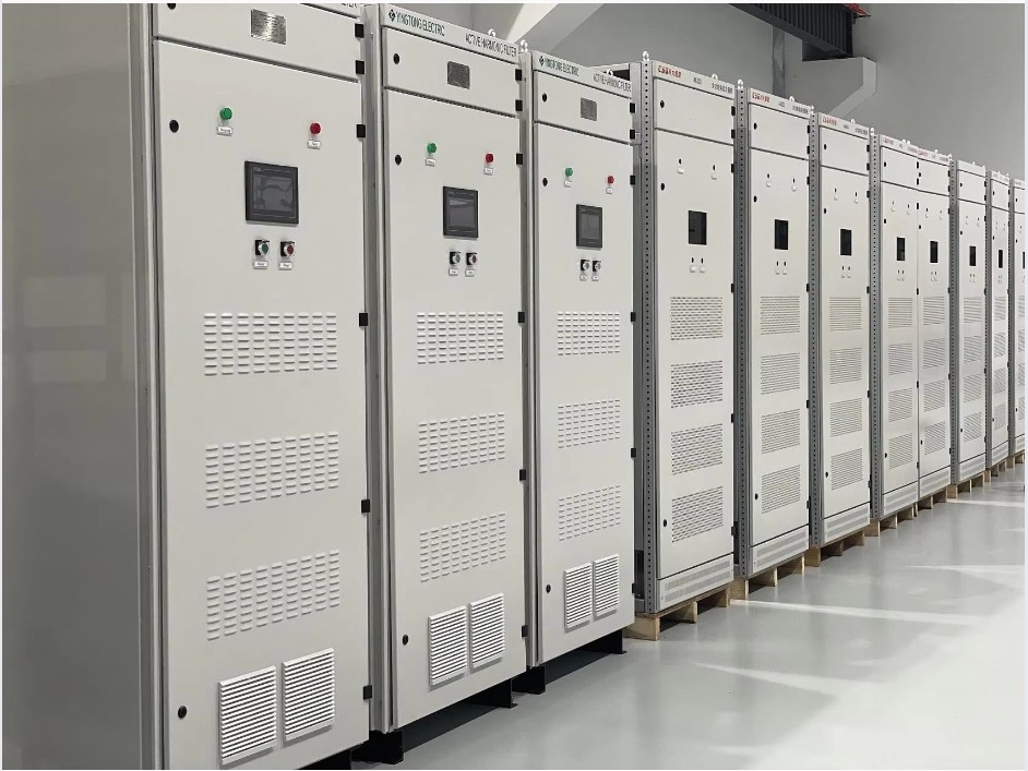
Alt Text: SiC MOSFET active harmonic filter with 3-level topology installed in a Southeast Asian textile mill for industrial THDi correction — YT Electric YTPQC-APF series wall-mount unit showing split-core CT connections, LCL filter section, and HMI touch panel display.
A Vietnamese textile group installed six YTPQC-APF units across three factories. Pre-installation measurements recorded THDi between 28% and 35% at the 400 V main bus. Post-installation THDi measured below 4.5% within 72 hours of commissioning.
Capacitor bank failures stopped immediately. Eliminated replacements, reduced utility penalties, and lower transformer K-factor losses saved approximately USD 42,000 in the first year across three sites.
The SiC MOSFET active harmonic filters operate continuously at 38–42°C ambient without derating. Annual maintenance — cleaning intake filters and verifying CT connections — takes approximately two hours per unit.
Do not specify AHF capacity from the transformer nameplate kVA. Measure the actual harmonic current spectrum at the PCC over a complete production cycle — minimum 24 hours. Size the AHF at 110–120% of the maximum measured harmonic current. YT Electric provides a free on-site power quality audit to determine the correct rating before procurement.
No. The AHF connects in parallel at the main distribution board. Use split-core CTs on live busbars. Terminate power cables at a spare circuit breaker. The entire installation and commissioning process runs 4–6 hours while production continues.
In markets with utility penalties for excessive harmonics — including Vietnam, Thailand, Indonesia, and the Philippines — payback ranges from 12 to 24 months. The calculation includes three components: elimination of penalty charges, reduction in transformer and cable I²R losses (1–3% of total load), and avoided equipment failure costs. Plants with recurring capacitor bank failures often recover the investment within 10 months.
Yes. The YTPQC-APF series rates for full-load operation at 45°C ambient without derating. The SiC MOSFET power modules generate approximately 30% less heat than equivalent Si IGBT modules. Redundant forced-air cooling handles heat rejection. The controller automatically reduces output current if internal IGBT/heatsink temperature exceeds 85°C — this is a protective trip limit, not an operating design constraint.
Southeast Asian manufacturing plants running VFD-heavy loads face a specific set of power quality problems: high THDi, capacitor bank resonance, and thermal stress in unregulated electrical rooms. A SiC MOSFET active harmonic filter addresses all three through semiconductor physics — lower switching losses, higher switching frequency, and full-load operation at 45°C ambient without derating.
YT Electric manufactures the YTPQC-APF series with 3-level SiC MOSFET topology, rated from 50 A to 600 A at 400 V and 690 V, available in wall-mount and floor-standing configurations. Contact our application engineering team with your single-line diagram and power quality measurement data for a site-specific proposal.



 IPv6 network supported