
 English
 français
 Deutsch
 español
 العربية
 中文
中文

As a deep practitioner in photovoltaic energy storage systems and power quality, Ying Tong will analyze how SVG (Static Var Generator) serves as the "voltage stabilizer" and "grid interaction hub" for PV-storage systems from problem-solving mechanisms and underlying physical principles. The following content is based on engineering validation and electromagnetic transient simulations:
I. Core Problems Solved by SVG & Working Principles
Problem 1: Voltage Flicker/Overlimit Caused by PV Fluctuation
- Scenario:
Cloud shading causes a 10MW PV plant’s output to drop from 8MW to 1MW in 2 seconds → 10% voltage sag at PCC.
- SVG Solution:
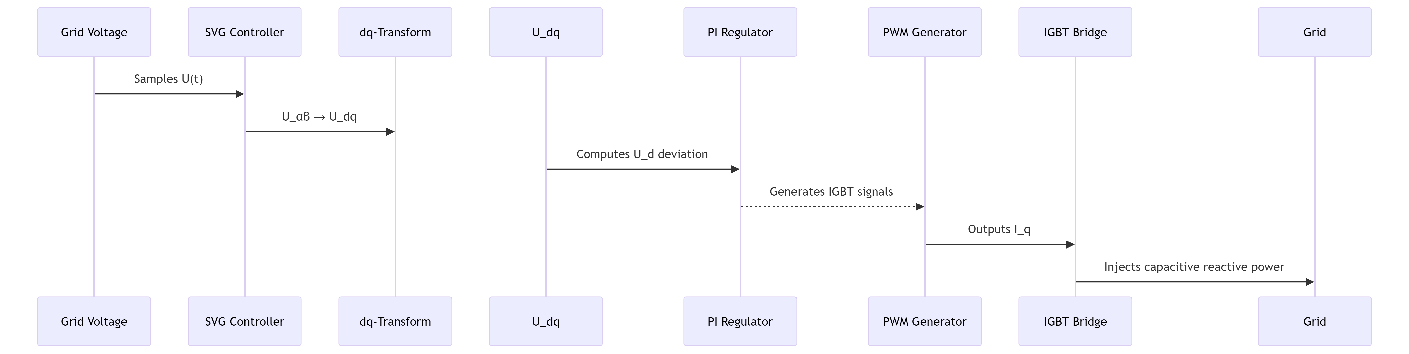
- Principle:
SVG detects voltage sag in real-time and instantly injects capacitive reactive current (\(I_q\)) via IGBT full-bridge circuits, counteracting voltage drop from line inductive reactance.
Voltage compensation formula:
Delta U = frac{Q_{SVG} \cdot X_L}{U_n}
- (X_L): Line impedance (Ω)
- (U_n): Rated voltage (V)
Example: For a 7% voltage drop (400V→372V), SVG injects 2Mvar capacitive reactive power within 10ms, restoring voltage to 392V (error <2%).
- Control Logic:
Problem 2: Power Factor Mutation During ESS Mode Switching
- Scenario:
ESS switches from charging (absorbing reactive power) to discharging (generating reactive power) → PF jumps from 0.95 lag to 0.9 lead.
- SVG Solution:
- Principle:
SVG operates in bidirectional quadrants:
- When PCS absorbs reactive power (inductive), SVG generates capacitive reactive power
- When PCS generates reactive power (capacitive), SVG absorbs excess reactive power
Power factor correction formula:
Q_{comp} = PESS cdot (tanϕ1 - tanϕ2)
- PESS: ESS active power (kW)
- ϕ1, ϕ2): PF angles before/after compensation
Example: For a 2MW ESS switching modes, SVG toggles ±0.8Mvar within 5ms.
Problem 3: Resonance Risk in Weak Grids
- Scenario:
Parallel resonance between PV inverters and SVG at 650Hz → background harmonics amplified by 200%.
- SVG Solution:
- Principle:
SVG embeds active damping algorithm:
1. Detect resonance frequency via FFT (e.g., 650Hz)
2. Inject virtual resistance (R_virtual) into control loop:
3. Reshapes grid impedance to suppress resonance peak <3%.
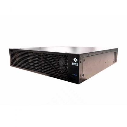
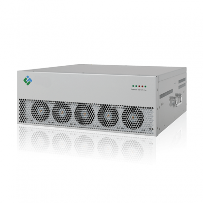
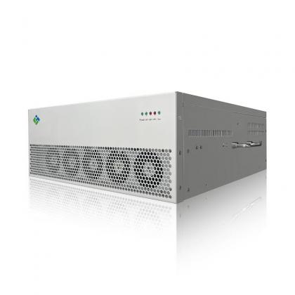
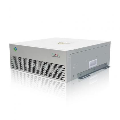
II. SVG Hardware Operating Principles
Core Topology (Three-Level NPC)
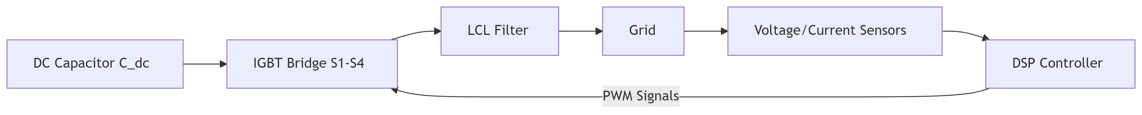
- Key Components:
- IGBT Bridge: Generates grid-synchronized reactive current via PWM
- LCL Filter: Attenuates switching harmonics (>2kHz, THD<3%)
- DC Capacitor: Stabilizes DC bus voltage (<5% ripple)
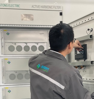
III. Collaborative Optimization Case
20MW PV + 5MW/10MWh ESS Project (Jiangsu)
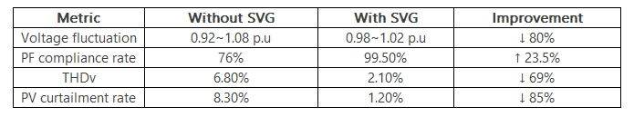
Key Actions:
- SVG pre-adjusts reactive power based on PV forecast (injects capacitive reactive before irradiance drop)
- Automatically switches to voltage support mode when ESS SOC<30%
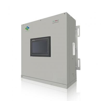
IV. Technical Selection Golden Rules
1. Capacity Redundancy:
Q_{SVG} = 1.3 \times (0.3P_{PV} + 0.4P_{ESS} + Q_{Load})
2. Response Speed: ≤15ms (control bandwidth >30Hz)
3. Protection Rating: IP54 + anti-corrosion coating (coastal/humid areas)
4. Harmonic Immunity: Stable operation at background THDv ≤8%
Ultimate Summary :
Static Var Generator (SVG) is fundamentally a controllable reactive source based on power electronics, achieving.


 IPv6 network supported