
The History Of Reactive Power Compensation
If you are in the power industry, you must have heard of reactive power compensation. But you may not know much about it.
What is reactive power compensation?
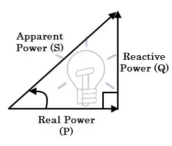
We know that the power output of the power grid includes two parts: first, active power: directly consume electric energy, convert electric energy into mechanical energy, thermal energy, chemical energy or sound energy, and use these energy to do work. This part of power is called active power; The second is reactive power: it consumes electric energy, but only converts it into another form of energy. This energy is a necessary condition for electrical equipment to work, and this energy is periodically converted with electric energy in the power grid. This part of power is called reactive power (such as the electric energy occupied by electromagnetic components to establish magnetic fields, and the electric energy occupied by capacitors to establish electric fields).
Reactive power can be expressed as
Q = S sin ϕ Q = VI sin ϕ Q = P tan ϕ Where S = apparent power and P = active power.
The History
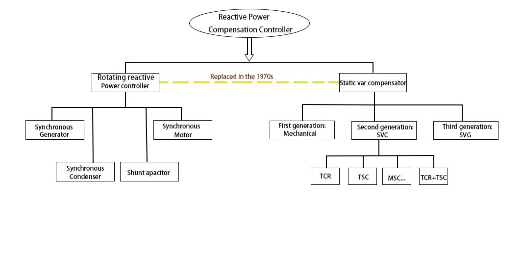
As shown in the classification diagram of reactive power compensation above, due to the problems of equipment manufacturing cost and equipment power consumption, static reactive power compensation technology began to replace rotating reactive power compensation technology in the 1970s, and now three generations of technological innovation have been carried out.
The first generation
The passive compensation devices with mechanical switching are slow reactive compensation devices, which are basically eliminated at present.
The second generation
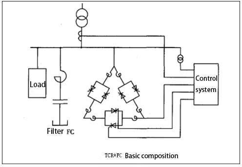
Static var compensator with thyristor switching, which belongs to passive fast var compensation device. At present, TCR and TSC are mainly used in the market, but the disadvantage is that they are prone to over compensation and under compensation, inconvenient capacity expansion, large heat dissipation of capacitor cabinet, etc. TCR: TCR adjusts the trigger angle of thyristor α, Realize continuous adjustment of reactive power of compensation device. Using the inductive reactive power absorbed by the TCR circuit, the reactive power can be dynamically compensated, so that the excess reactive power in the parallel filter can be balanced, and the voltage at the compensation point is close to maintaining unchanged. Its basic composition is shown in Figure below.
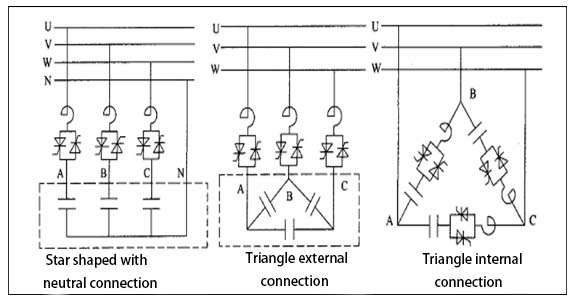
TSC: generally, the filter of multiple branches is designed according to a certain proportion, which is capacitive at the fundamental frequency, and the reactive power output of the compensation device changes in stages. The filter branch offsets and tunes under certain harmonics, and filters the harmonics at the same time. TSC can only be switched in groups and must be coordinated with TCR for continuous adjustment. TSC has three basic circuits, as shown in figure. Figure left shows the star with neutral connection, figure mid shows the external connection of triangle, which is called angular external connection, and figure right shows the internal connection of triangle, which is called angular internal connection. On the basis of these three circuits, many other topologies are derived, such as replacing the thyristor in each phase with a diode, or removing the thyristor switch of a phase to save cost. The selection of topology should be comprehensively considered in combination with the actual situation of on-site load and technical and economic factors.
The third generation
Static Var Generator(SVG, etc.) of self reversing converter is the best var compensation device at present. This kind of device usually works by connecting the self commutating bridge circuit in parallel with the power grid. By adjusting the phase and amplitude of the output voltage on the AC side of the bridge circuit, or directly controlling its AC side current, the circuit can absorb or send out reactive current that meets the requirements, so as to realize the purpose of dynamic reactive power compensation.
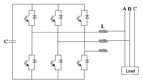
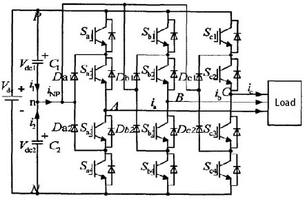
Two level basic circuit diagram Three level basic circuit diagram
YT Power Quality Solutions
Based on the principle of voltage source inverter, YTPQC-SVG static var generator adopts insulated gate bipolar transistor (IGBT) to control the amplitude and phase of AC voltage of the inverter, so as to realize reactive power compensation and three-phase load balance. Because the switching frequency of IGBT is very high (up to 25.6khz), SVG can compensate fast reactive load and realize high-precision compensation. SVG is the best product in the field of reactive power control.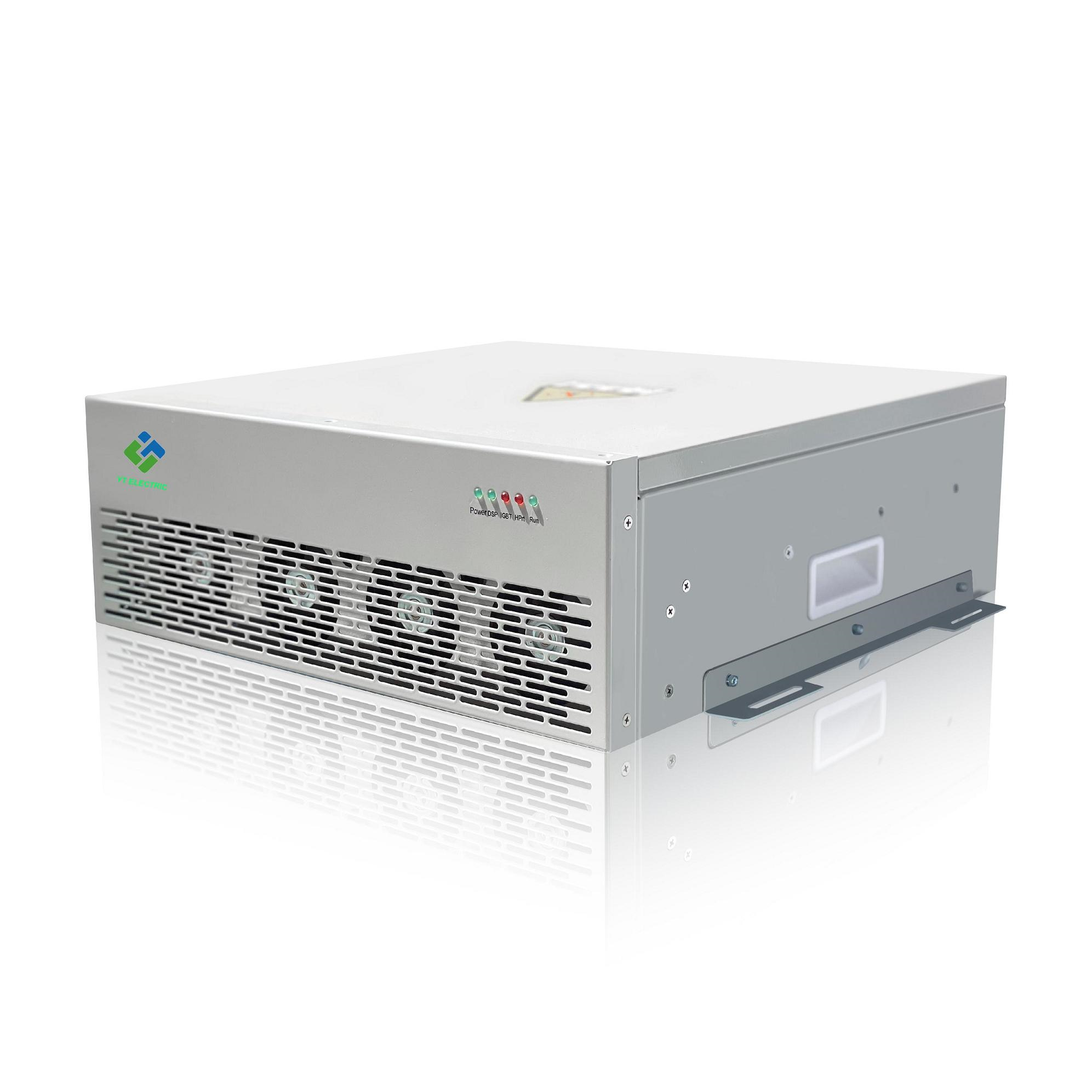
Subscribe to us to enjoy event prices and get some of the best prices.
 IPv6 network supported

